Multi-output switching power supply
a power supply and multi-output technology, applied in the direction of electric variable regulation, process and machine control, instruments, etc., can solve the problems of increasing the cost and mounting area, increasing the loss caused by the regulator b>12/b>, and becoming more difficult to obtain the required voltag
- Summary
- Abstract
- Description
- Claims
- Application Information
AI Technical Summary
Benefits of technology
Problems solved by technology
Method used
Image

Examples
embodiment 1
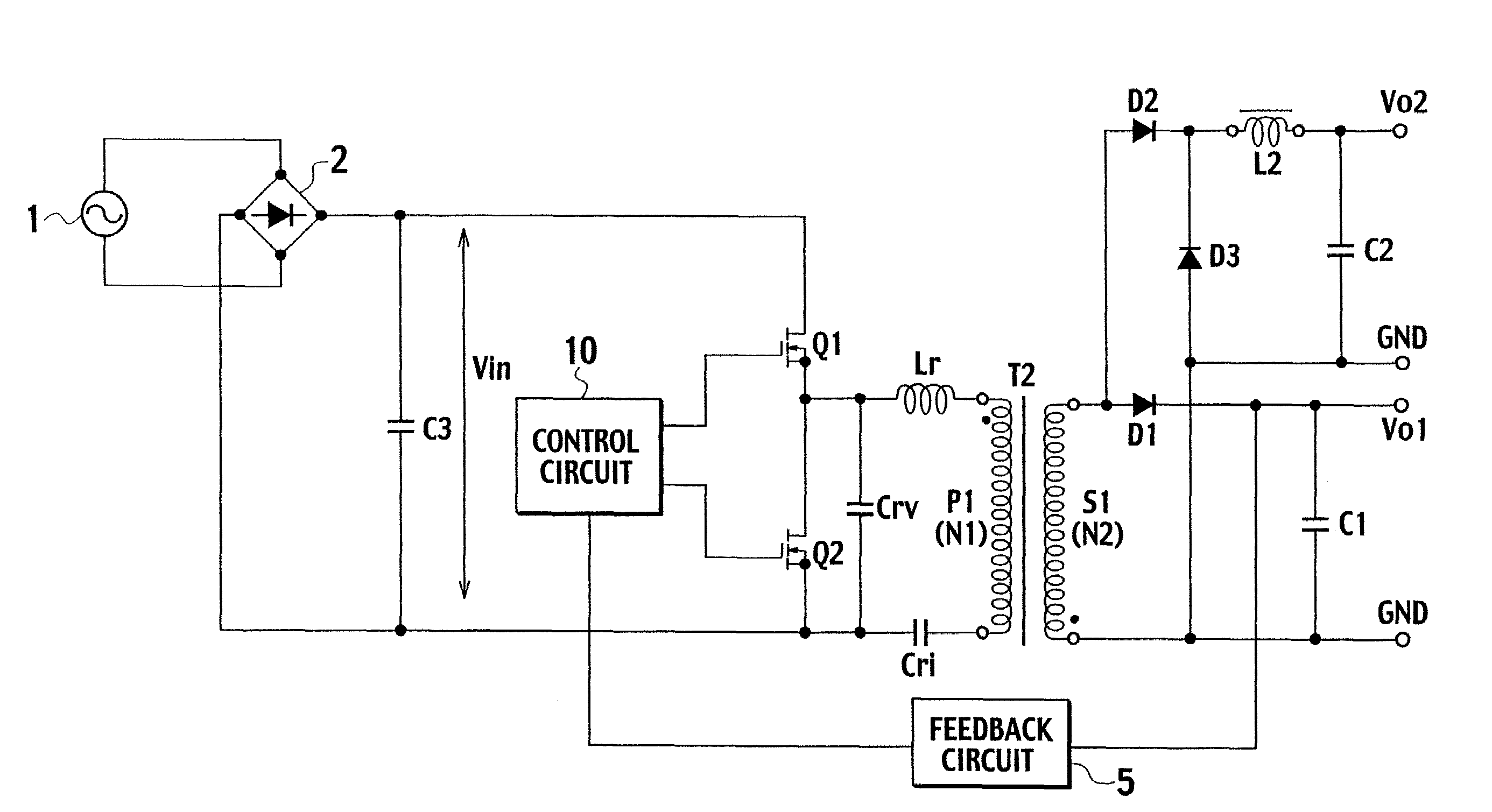
[0044]FIG. 4 is a circuit diagram showing a configuration of a multi-output switching power supply according to Embodiment 1 of the present invention. The configuration of the multi-output switching power supply shown in FIG. 4 is different from that of the conventional multi-output switching power supply shown in FIG. 1 only in a constituent component connected to a second secondary winding S2 of a transformer T1. Thus, only a configuration of this component described above will be described.
[0045]An anode of a diode D2 is connected to one end of the second secondary winding S2 of the transformer T1, and an anode of a diode D3 is connected to the other end of the second secondary winding S2 of the transformer T1. A cathode of the diode D2 and a cathode of the diode D3 are connected to one end of a reactor L2, and the other end of the reactor L2 is connected to a second output terminal. A smoothing capacitor C2 is connected between the other end of the reactor L2 and the other end (...
embodiment 2
[0059]FIG. 6 is a circuit diagram showing a configuration of a multi-output switching power supply according to Embodiment 2 of the present invention. The configuration of Embodiment 2 shown in FIG. 6 is different from that of Embodiment 1 shown in FIG. 4 in having a transformer T2 having a primary winding P1 and a secondary winding S1 and in the following point. Specifically, an anode of a diode D2 is connected to a connection point between the secondary winding S1 and an anode of a diode D1. Moreover, a GND terminal of a second output voltage Vo2 and an anode of a diode D3 are commonly connected to a GND terminal of a first output voltage Vo1.
[0060]By use of the multi-output switching power supply thus configured according to Embodiment 2, in an on period of a second switching element Q2, a voltage VS1=Vo1+Vf (Vf is a forward voltage drop of the diode D1) is generated in the secondary winding S1. This voltage VS1 causes a current ID2 and a current IL2 to flow through S1, D2, L2, C...
embodiment 3
[0062]FIG. 7 is a circuit diagram showing a configuration of a multi-output switching power supply according to Embodiment 3 of the present invention. The configuration of Embodiment 3 shown in FIG. 7 is different from that of Embodiment 1 shown in FIG. 4 in that a polarity of a second secondary winding S2 of a transformer T1 is inverted.
[0063]Next, with reference to a waveform diagram shown in FIG. 8, description will be given of operations of the multi-output switching power supply thus configured according to Embodiment 3 of the present invention.
[0064]In an on period of a second switching element Q2, a voltage of Vn2off=Vo1+Vf is generated in a secondary winding S1 only for a period of toff=Doff / f. Since voltage time products of positive and negative voltages generated in the secondary winding S1 of the transformer T1 are equal, a voltage of Vn2on=Vn2off×toff / ton is generated in the secondary winding S1 in an on period ton of a first switching element Q1.
[0065]In the on period (...
PUM
 Abstract
Description
Claims
Application Information
 - R&D
- Intellectual Property
- Life Sciences
- Materials
- Tech Scout
- Unparalleled Data Quality
- Higher Quality Content
- 60% Fewer Hallucinations
Browse by: Latest US Patents, China's latest patents, Technical Efficacy Thesaurus, Application Domain, Technology Topic, Popular Technical Reports.
© 2025 PatSnap. All rights reserved.Legal|Privacy policy|Modern Slavery Act Transparency Statement|Sitemap|About US| Contact US: help@patsnap.com