Magnetic disk device and head-position control method
a magnetic disk and control method technology, applied in adaptive control, process and machine control, instruments, etc., can solve the problems of inability to implement this technique, inability to suppress the excitation of mechanical resonance, and inability to calculate the feedforward control input for the actuator and the target position command
- Summary
- Abstract
- Description
- Claims
- Application Information
AI Technical Summary
Benefits of technology
Problems solved by technology
Method used
Image

Examples
first embodiment
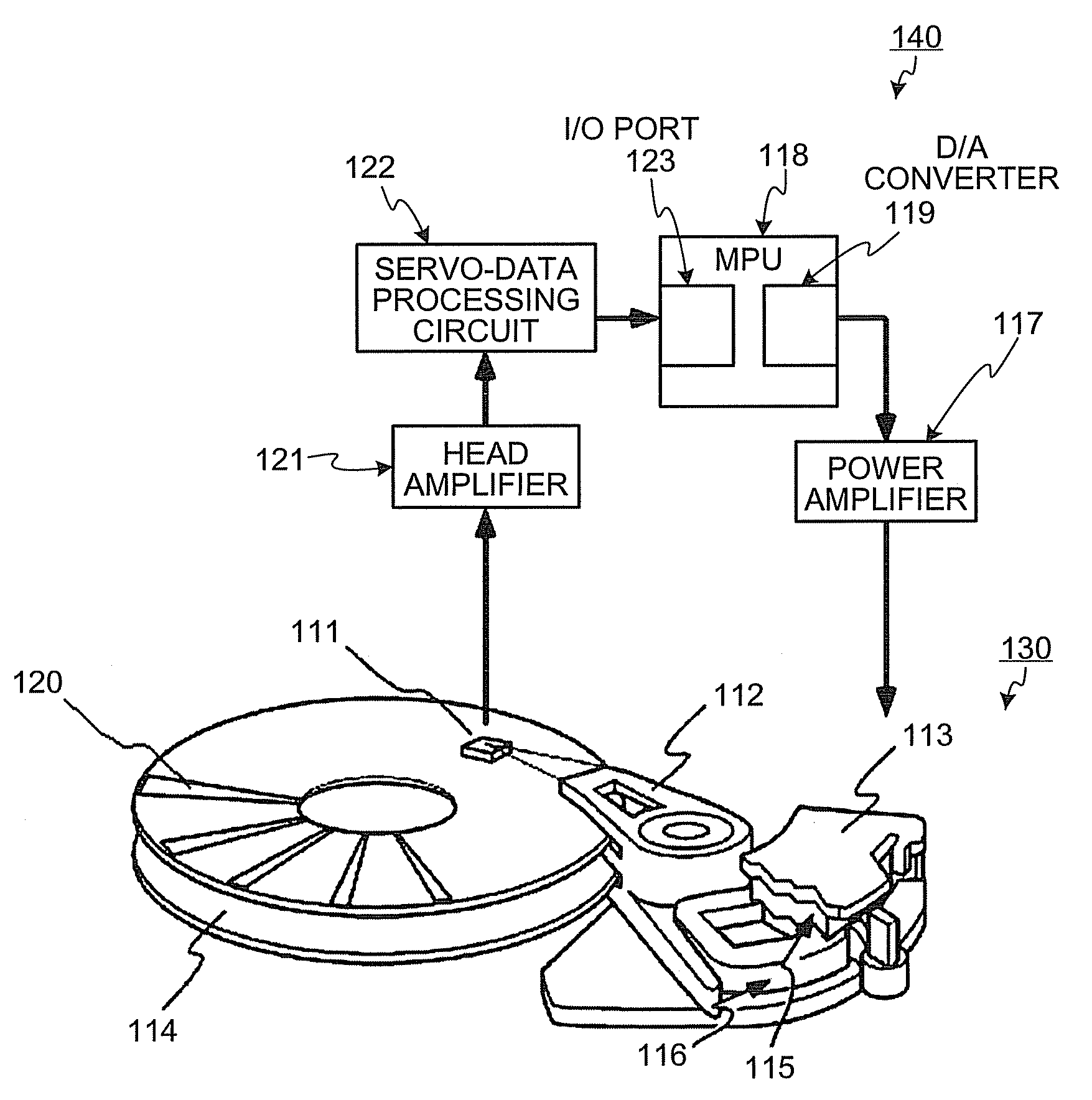
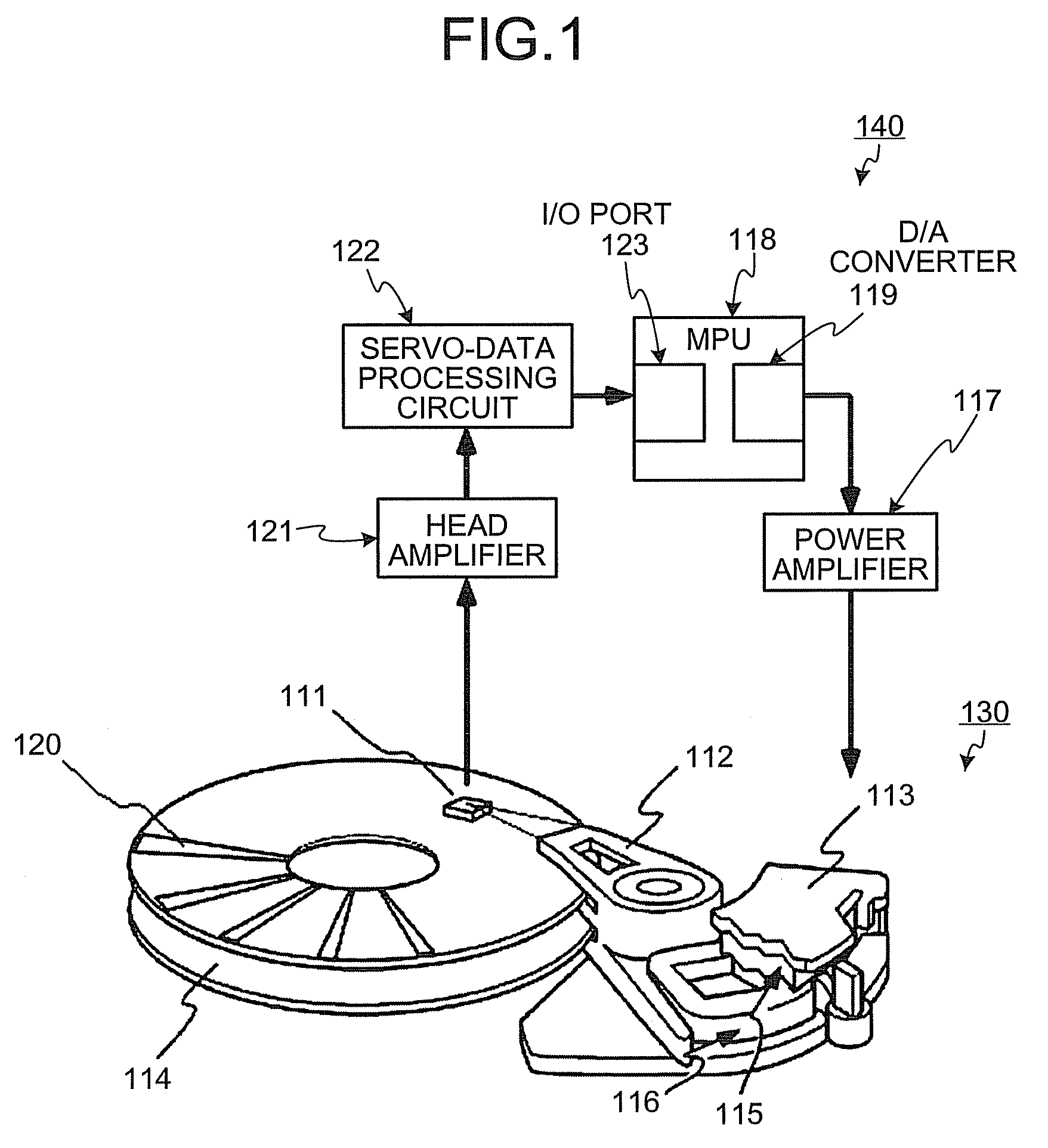
[0032]An HDD includes a hard disk (HD) 114, an actuator 130, and an HDD controller 140, as shown in FIG. 1. Specifically, the actuator 130 has mechanisms such as a magnetic head 111, an arm 112, and a voice coil motor (VCM) 113. The HDD controller 140 is provided as a control circuit having a head-positioning control mechanism on a printed board in the hard disk drive.
[0033]At least one of the HD 114 is provided for the HDD, and is rotated at high speed by a spindle motor. A plurality of tracks are concentrically formed on the HD 114, and each track has servo areas 120 formed at predetermined intervals. Track position information is previously embedded in each of the servo areas 120, and a data sector is provided between the servo areas 120 to record user data therein.
[0034]As shown in FIG. 1, the head 111 is held by the arm 112 in the actuator 130. The head 111 reads the track position information from the servo area 120, or reads the user data from the data sector. The arm 112 is...
second embodiment
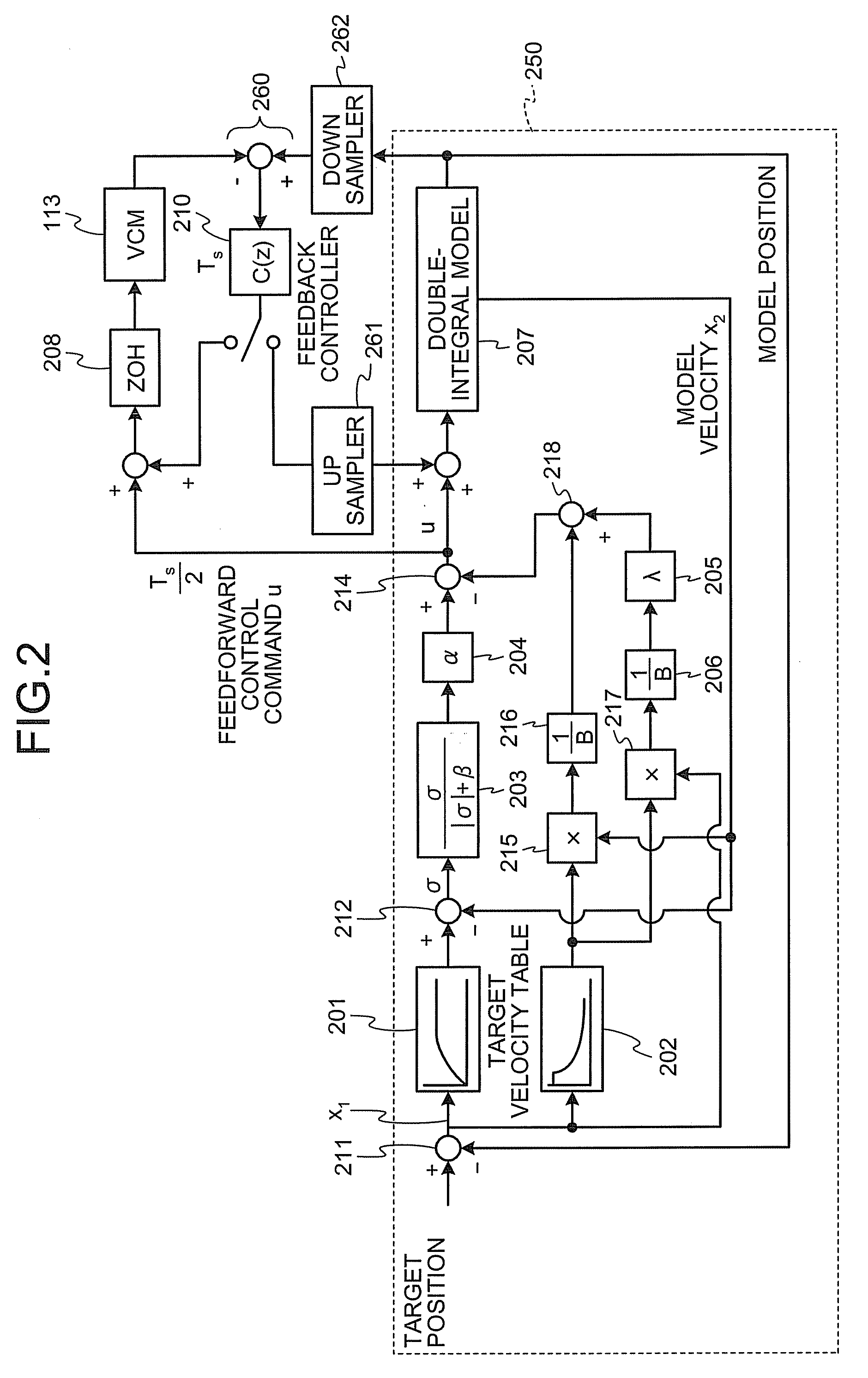
[0127]In the head-positioning control system for the hard disk drive the model-side control system is configured by using the differential value df(x1) / dx1 of the target velocity with respect to the remaining distance x1, and the feedforward control command u required for the model velocity x2 to follow the target velocity is generated by using the remaining distance x1 corresponding to the target velocity. Thus, the following capability of the model velocity to the target velocity can be improved, and excitation of mechanical resonance can be suppressed by smoothly switching the control command from acceleration to deceleration.
[0128]A hard disk drive according to the third embodiment is different from that of the first and the second embodiments in the method of calculating the control command u in the head-positioning control system.
[0129]The head-positioning control system according to the third embodiment also has two control loops such as a model-side control system 2750 and ...
third embodiment
[0135]In the head-positioning control system for the hard disk-drive the model-side control system is configured by using the differential value df(x1) / dx1 of the target velocity with respect to the remaining distance x1, and the feedforward control command u required for the model velocity x2 to follow the target velocity is generated by using the remaining distance x1 corresponding to the target velocity. Thus, the following capability of the model velocity to the target velocity can be improved, and excitation of mechanical resonance can be suppressed by smoothly switching the control command from acceleration to deceleration.
PUM
| Property | Measurement | Unit |
|---|---|---|
| velocity | aaaaa | aaaaa |
| distance | aaaaa | aaaaa |
| frequency | aaaaa | aaaaa |
Abstract
Description
Claims
Application Information
 - R&D
- Intellectual Property
- Life Sciences
- Materials
- Tech Scout
- Unparalleled Data Quality
- Higher Quality Content
- 60% Fewer Hallucinations
Browse by: Latest US Patents, China's latest patents, Technical Efficacy Thesaurus, Application Domain, Technology Topic, Popular Technical Reports.
© 2025 PatSnap. All rights reserved.Legal|Privacy policy|Modern Slavery Act Transparency Statement|Sitemap|About US| Contact US: help@patsnap.com