Zoom lens and imaging apparatus
a zoom lens and imaging apparatus technology, applied in the field of zoom lenses and imaging apparatuses, can solve the problems of affecting the compactness of the image, and the difficulty of earlier developed zoom lenses to meet all the higher zooming power, so as to achieve the effect of higher zooming power and higher image quality
- Summary
- Abstract
- Description
- Claims
- Application Information
AI Technical Summary
Benefits of technology
Problems solved by technology
Method used
Image

Examples
first embodiment
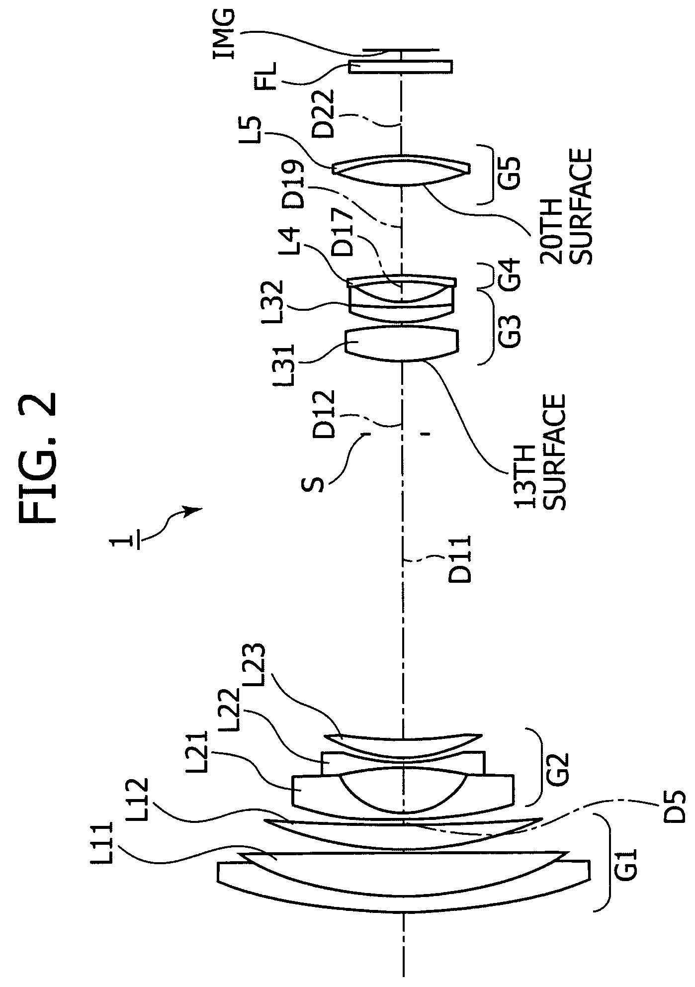
[0117]FIG. 2 is a diagram showing the lens construction of a zoom lens 1 according to the present invention. A first lens group G1 is constructed by positioning, in the order from the object side to the image-plane side, a cemented lens L11 formed of a meniscus-shaped negative lens having a convex surface facing the object side and a positive lens having a convex surface facing the object side, and a positive lens L12 having a convex surface facing the object side. A second lens group G2 is constructed by positioning, in the order from the object side to the image-plane side, a meniscus-shaped negative lens L21 having a concave surface facing the image side, a biconcave negative lens L22, and a positive lens L23 having a convex surface facing the object side. A third lens group G3 is constructed by positioning, in the order from the object side to the image-plane side, a biconvex positive lens L31 having a convex surface facing the object side and having the object-side surface form...
second embodiment
[0131]FIG. 7 is a diagram showing the lens construction of a zoom lens 2 according to the present invention. A first lens group G1 is constructed by positioning, in the order from the object side to the image-plane side, a cemented lens L11 formed of a meniscus-shaped negative lens having a convex surface facing the object side and a positive lens having a convex surface facing the object side, and a positive lens L12 having a convex surface facing the object side. A second lens group G2 is constructed by positioning, in the order from the object side to the image-plane side, a meniscus-shaped negative lens L21 having a concave surface facing the image side, a biconcave negative lens L22, and a positive lens L23 having a convex surface facing the object side. A third lens group G3 is constructed by positioning, in the order from the object side to the image-plane side, a biconvex positive lens L31 having a convex surface facing the object side and having the object-side surface form...
third embodiment
[0145]FIG. 12 is a diagram showing the lens construction of a zoom lens 3 according to the present invention. A first lens group G1 is constructed by positioning, in the order from the object side to the image-plane side, a cemented lens L11 formed of a meniscus-shaped negative lens having a convex surface facing the object side and a positive lens having a convex surface facing the object side, a positive lens L12 having a convex surface facing the object side, and a positive lens L13 having a convex surface facing the object side. A second lens group G2 is constructed by positioning, in the order from the object side to the image-plane side, a meniscus-shaped negative lens L21 having a concave surface facing the image side, a biconcave negative lens L22, and a positive lens L23 having a convex surface facing the object side. A third lens group G3 is constructed by positioning, in the order from the object side to the image-plane side, a biconvex positive lens L31 having a convex s...
PUM
 Abstract
Description
Claims
Application Information
 - R&D
- Intellectual Property
- Life Sciences
- Materials
- Tech Scout
- Unparalleled Data Quality
- Higher Quality Content
- 60% Fewer Hallucinations
Browse by: Latest US Patents, China's latest patents, Technical Efficacy Thesaurus, Application Domain, Technology Topic, Popular Technical Reports.
© 2025 PatSnap. All rights reserved.Legal|Privacy policy|Modern Slavery Act Transparency Statement|Sitemap|About US| Contact US: help@patsnap.com