Image sensor, focal point detection device and camera
a detection device and image sensor technology, applied in the direction of cameras, printers, instruments, etc., can solve the problems of increasing the bulk and cost of the devi
- Summary
- Abstract
- Description
- Claims
- Application Information
AI Technical Summary
Benefits of technology
Problems solved by technology
Method used
Image


Examples
first embodiment
[0037]FIG. 1 shows a camera that includes the focal point detection device achieved in the first embodiment of the present invention. This focal point detection device adopts the phase difference detection method to detect the state of focal adjustment achieved at a photographic lens 1 mounted at a single lens reflex camera 100. It is to be noted that in the camera 100, a photographing operation unit 101 is engaged in operation in response to a shutter release signal and a subject image is recorded at a film type image-capturing device, as known in the related art.
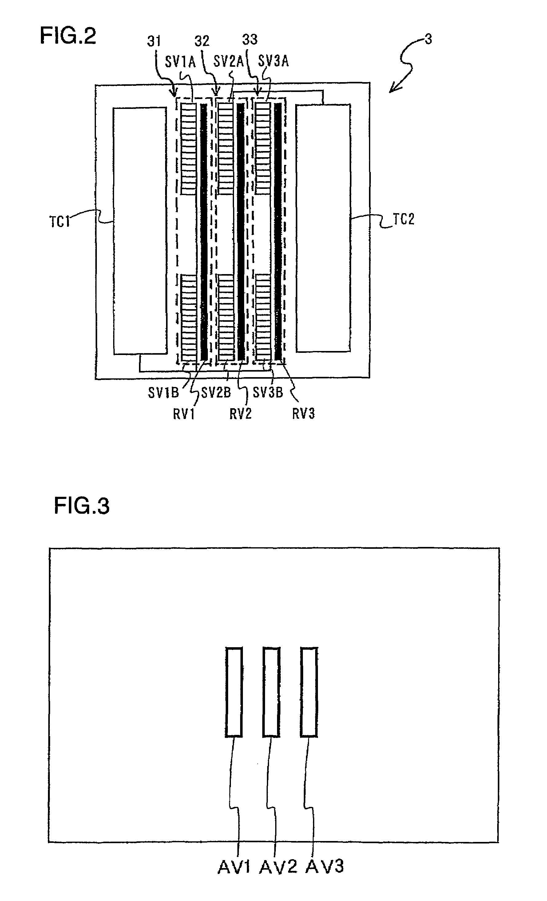
[0038]As the light having originated from the photographic field and passed through the photographic lens 1 enters a focal point detection optical system 2, three pairs of subject images are formed at an image sensor module 3 with light fluxes in the light from the photographic field, the ranges of which each correspond to one of three focal point detection areas set within the photographic image plane. The subject images ...
second embodiment
[0059]FIG. 5 shows focal point detection areas set within the photographic image plane in the second embodiment. Since the structure of the camera 100 is similar to that adopted in the first embodiment, its explanation is omitted and the following explanation focuses on the focal point detection areas and the corresponding photoelectric conversion devices.
[0060]In the first embodiment, three focal point detection areas AV1, AV2 and AV3 are set within the photographic image plane and the storage operations at the two photoelectric conversion devices 31 and 33 respectively corresponding to the focal point detection areas AV1 and AV3 which are not set directly next to each other are commonly controlled by a single storage control circuit TC1. In the second embodiment, nine focal point detection areas LV1, LV2, LV3, CV1, CV2, CV3, RV1, RV2 and RV3 are set within the photographic image plane as shown in FIG. 5. In conjunction with these focal point detection areas, a single storage contr...
third embodiment
[0064]FIG. 6 shows focal point detection areas set within the photographic image plane in the third embodiment. Since the structure of the camera 100 is similar to that adopted in the first embodiment, its explanation is omitted and the following explanation focuses on the focal point detection areas and the corresponding photoelectric conversion devices.
[0065]FIG. 6 shows the sixteen focal point detection areas set within the photographic image plane, which are divided into separate area groups (blocks) L, HV and R. Focal point detection areas H1, H2, H3, H4 and H5 in the area group HV are set in a lateral orientation, whereas the other focal point detection areas in the area group HV are set in a longitudinal orientation. In other words, the photoelectric conversion devices corresponding to the focal point detection areas H1, H2, H3, H4 and H5 are set along a direction forming a 90° angle relative to the direction of the photoelectric conversion devices corresponding to the remain...
PUM
 Abstract
Description
Claims
Application Information
 - R&D
- Intellectual Property
- Life Sciences
- Materials
- Tech Scout
- Unparalleled Data Quality
- Higher Quality Content
- 60% Fewer Hallucinations
Browse by: Latest US Patents, China's latest patents, Technical Efficacy Thesaurus, Application Domain, Technology Topic, Popular Technical Reports.
© 2025 PatSnap. All rights reserved.Legal|Privacy policy|Modern Slavery Act Transparency Statement|Sitemap|About US| Contact US: help@patsnap.com