Body support structure of a vehicle
a technology for supporting structures and vehicles, applied in vehicle arrangements, roofs, transportation and packaging, etc., to achieve the effect of large increase in weight and efficient transmission of load
- Summary
- Abstract
- Description
- Claims
- Application Information
AI Technical Summary
Benefits of technology
Problems solved by technology
Method used
Image

Examples
first embodiment
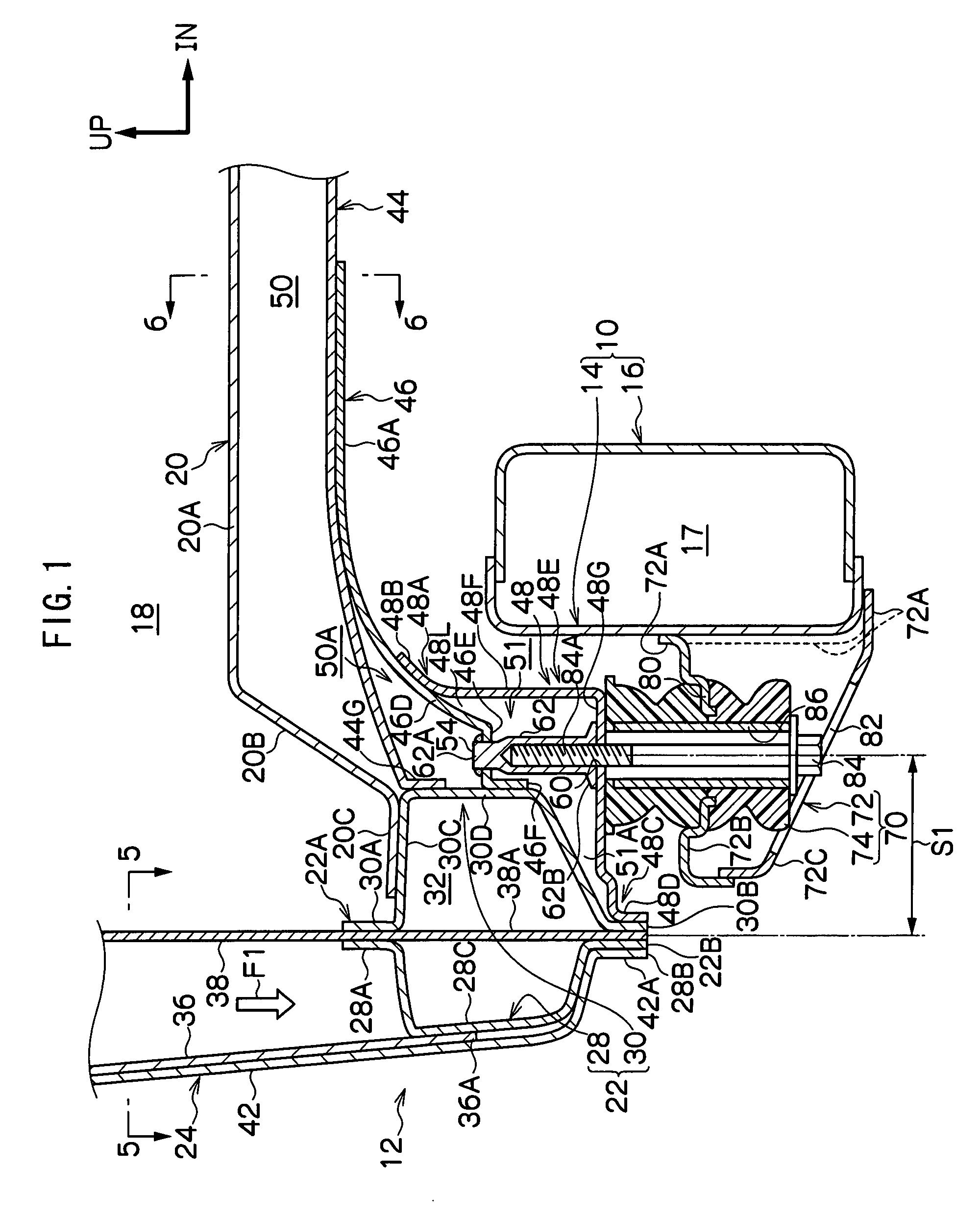
[0017]the body support structure of a vehicle of the present invention will be described in association with FIG. 1 to FIG. 5.
[0018]Note that, in the drawings, the arrow UP indicates an upward direction of the vehicle, the arrow FR indicates a forward direction of the vehicle and the arrow IN indicates an inward direction of the vehicle.
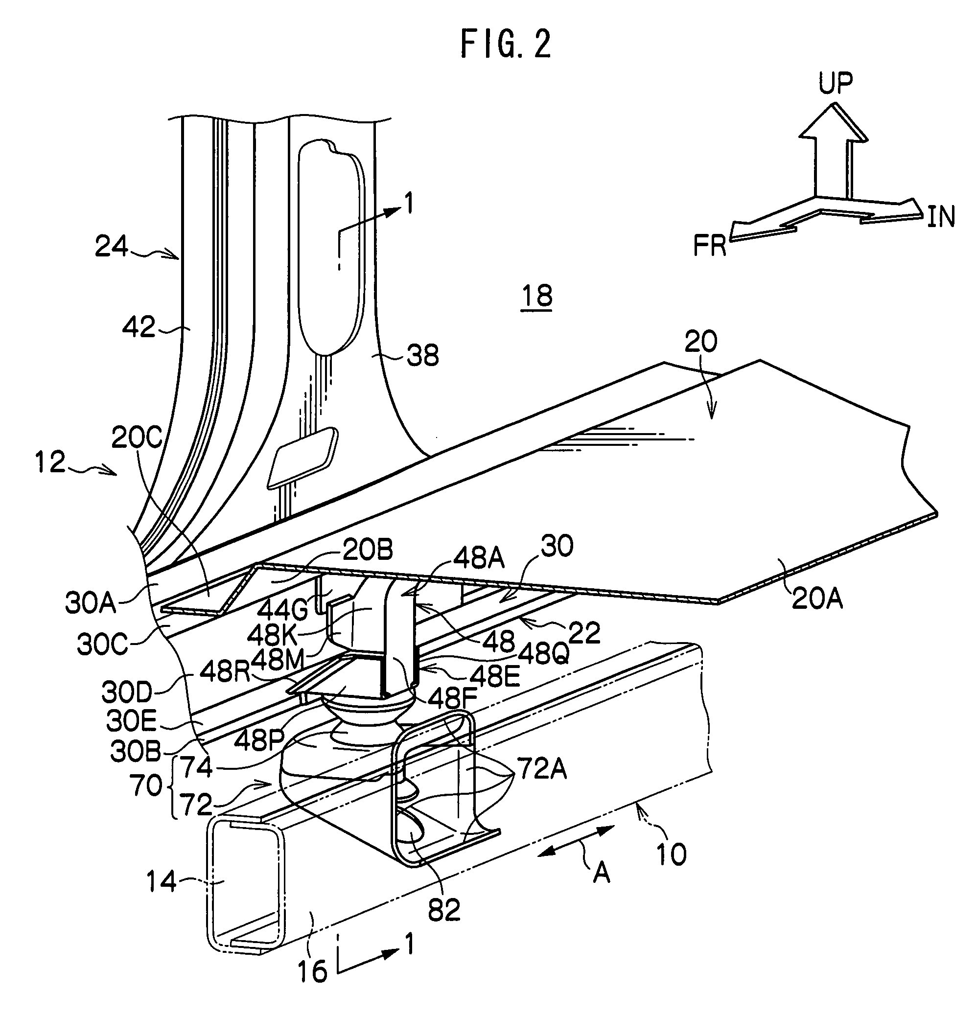
[0019]FIG. 2 shows the vehicle body support structure relating to the first embodiment of the present invention, in a perspective view seen from above in a forward-inward diagonal direction of the vehicle.
[0020]In FIG. 2, a chassis frame 10 is shown by broken lines in order to clarify structure.
[0021]As shown in FIG. 2, an automobile of the present embodiment is provided with a pair of the chassis frame 10 at left and right. The chassis frames 10 are disposed along a vehicle longitudinal direction at lower portions of two lateral direction ends of the vehicle. The structure of the automobile is also provided with a body 12, which rests on the chassis...
second embodiment
[0059]Next, the body support structure of a vehicle of the present invention will be described in association with FIG. 6.
[0060]Here, members that are the same as in the first embodiment are assigned the same reference numerals, and descriptions thereof will not be given.
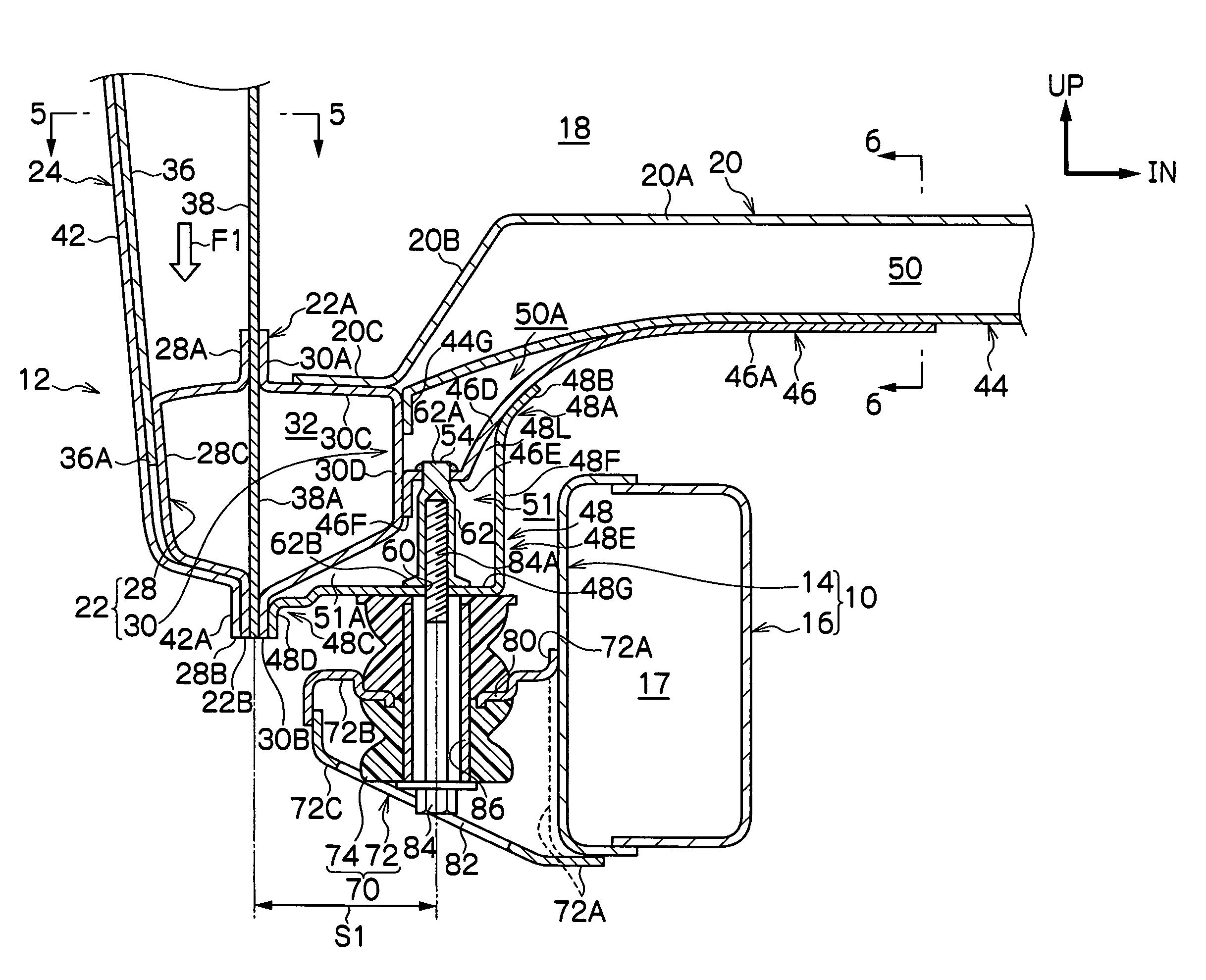
[0061]FIG. 6 shows a sectional view, corresponding to FIG. 1, of the vehicle body support structure relating to the second embodiment of the present invention.
[0062]As shown in FIG. 6, in the present embodiment, a bulkhead 90 is provided to serve as a reinforcing member in the closed section structure that is formed by the rocker inner 30 and the center pillar inner panel 38 at the closed section structure 32 of the rocker 22. A flange 90A, which is formed at a peripheral edge portion of the bulkhead 90, is joined with the rocker inner 30 and the center pillar inner panel 38 by welding or the like.
[0063]The bulkhead 90 is disposed at a position of attachment of the mount bracket 48 to the rocker inner 30. More speci...
PUM
 Abstract
Description
Claims
Application Information
 - R&D
- Intellectual Property
- Life Sciences
- Materials
- Tech Scout
- Unparalleled Data Quality
- Higher Quality Content
- 60% Fewer Hallucinations
Browse by: Latest US Patents, China's latest patents, Technical Efficacy Thesaurus, Application Domain, Technology Topic, Popular Technical Reports.
© 2025 PatSnap. All rights reserved.Legal|Privacy policy|Modern Slavery Act Transparency Statement|Sitemap|About US| Contact US: help@patsnap.com