Check patentability & draft patents in minutes with Patsnap Eureka AI!

Electric motor cooling

a technology of electric motors and cooling rotors, which is applied in the direction of mechanical energy handling, magnetic circuit rotating parts, magnetic circuit shape/form/construction, etc., can solve the problems of reducing engine performance, affecting motor performance, and difficult cooling of rotors, so as to increase the gap, improve the efficiency of use, and improve the effect of efficiency

Active Publication Date: 2010-06-08
HAMILTON SUNDSTRAND CORP
View PDF20 Cites 10 Cited by
  • Summary
  • Abstract
  • Description
  • Claims
  • Application Information

AI Technical Summary

Benefits of technology

This approach allows independent control of cooling flows to the stator and rotor, reducing the need for high-pressure air and improving overall cooling efficiency by optimizing the use of cooling sources and maintaining motor performance.

Problems solved by technology

Often high pressure cooled bleed air is used as the motor cooling source, which reduces engine performance.
The size of the gap between the stator and rotor affects the motor performance.
However, minimizing the gap restricts the flow of cooling air, which makes cooling the rotor more difficult.
As a result, high pressure air is required to force the cooling flow through the gap.
As a result, the overall efficiency of the cooling arrangement suffers from providing unneeded high pressure air to the stator.

Method used


Image

  • Electric motor cooling
  • Electric motor cooling
  • Electric motor cooling

Examples


Embodiment Construction

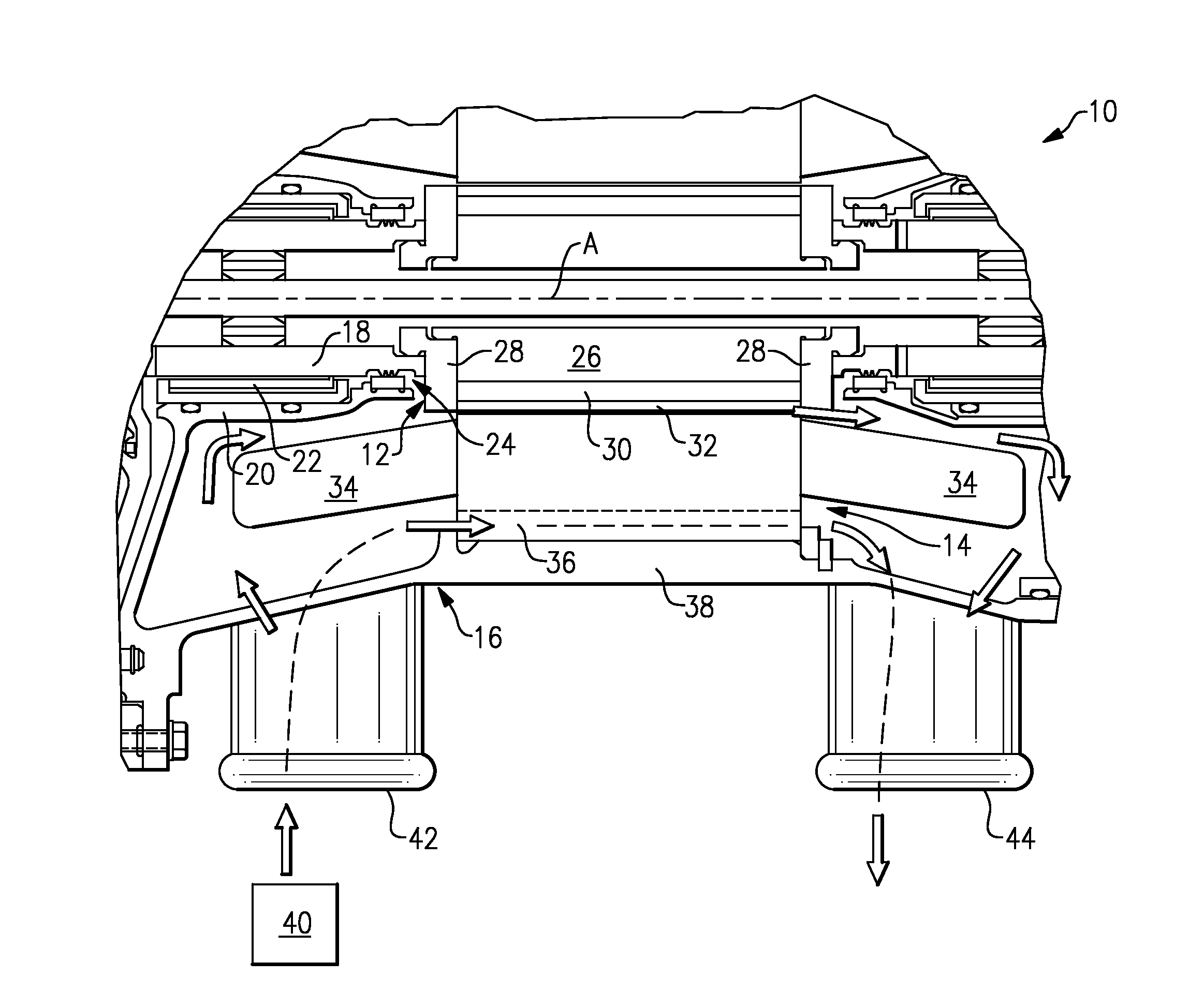
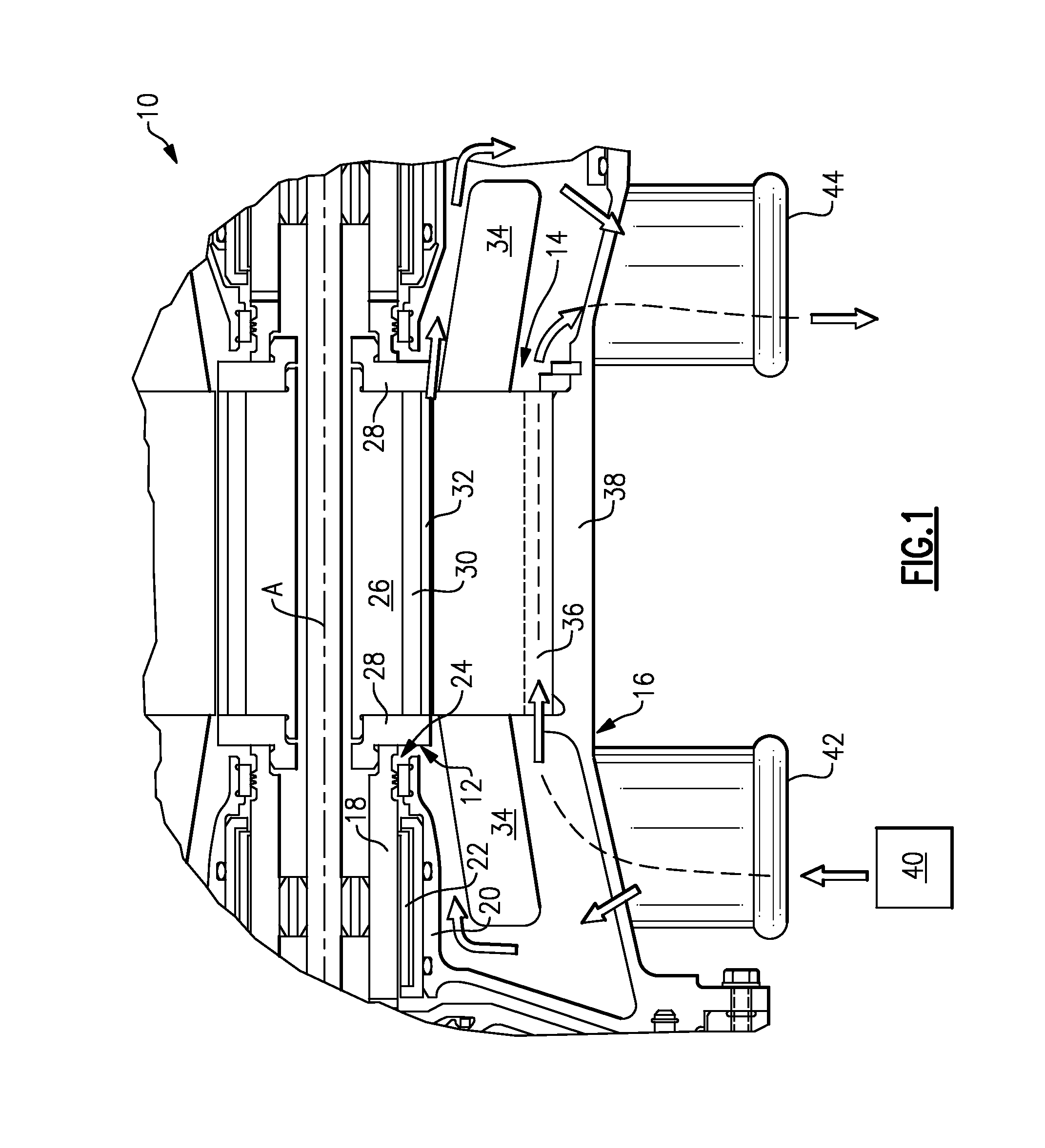
[0016]An electric motor 10 is shown in FIG. 1. The electric motor 10 can be used to drive an aircraft compressor, for example. The motor 10 includes a stator 14 mounted in a housing 16. A rotor 12 rotates about an axis A relative to the stator 14, as is known art.

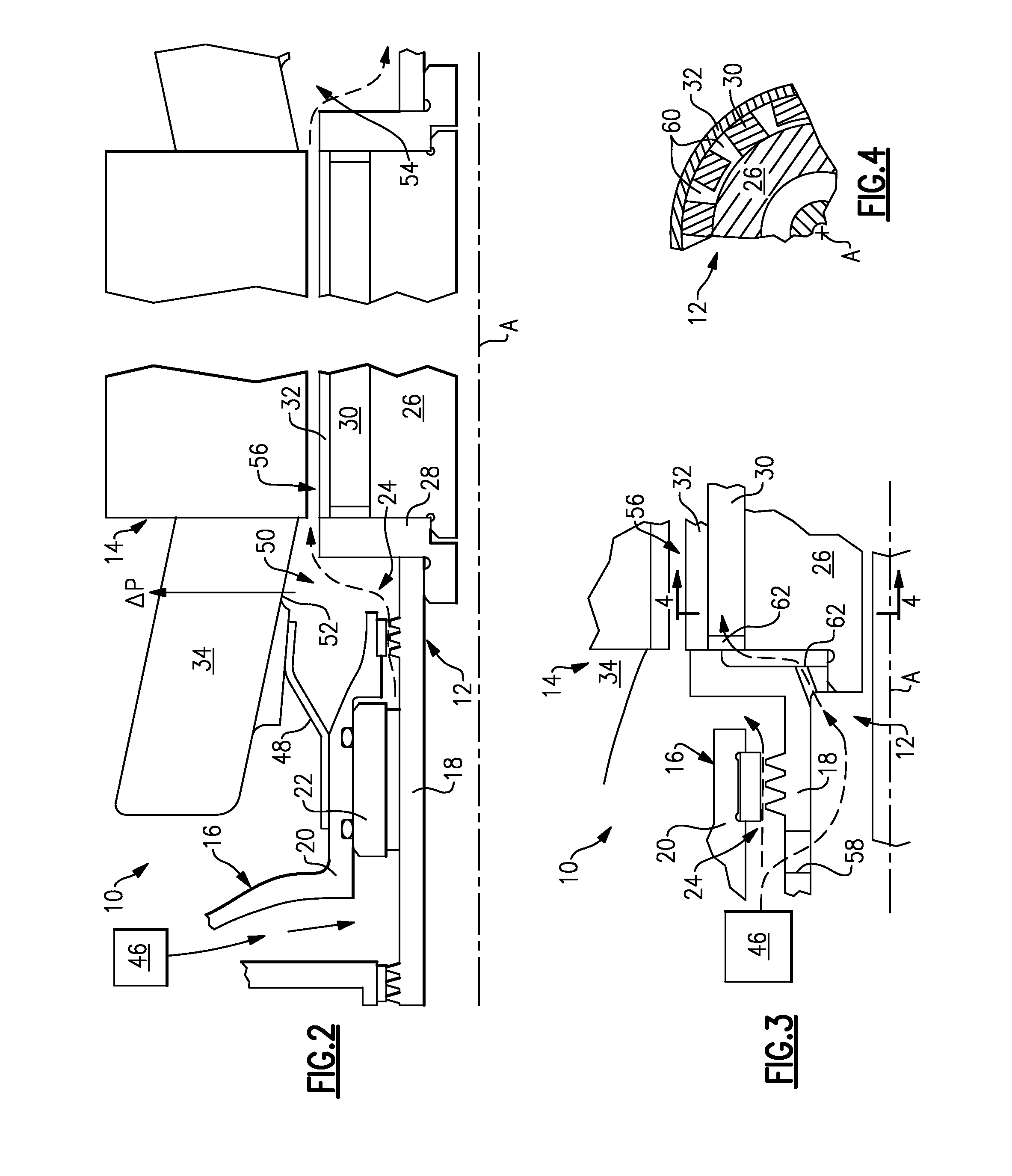
[0017]The rotor 12 includes a shaft 18 that is supported by a journal bearing 22 mounted in a first housing portion 20. A seal assembly 24 is arranged between the shaft 18 and the first housing portion 20. In the example shown, the seal assembly 24 is a knife edge seal arrangement. The rotor 12 includes a hub 26 retained between end caps 28 that are supported by the shaft 18. Magnets 30 are arranged circumferentially about the hub 26 and encased by a liner 32.

[0018]The stator 14 is provided by windings that include end turns 34. In the example, the stator 14 includes axially extending slots 36 that provide cooling channels arranged between the stator 14 and a second housing portion 38. A first cooling source 40, such as ram...


PUM


Abstract

An electric motor cooling system is provided that includes a housing and first and second cooling sources that are different from one another respectively to provide first and second cooling flows. A stator is mounted in the housing and receives the first cooling flow. A rotor is rotatable relative to the stator and receives the second cooling flow. In the examples, the housing supports a journal bearing upon which the rotor is supported, and the second cooling flows through the journal bearing. The first cooling flow is provided by a low pressure source such as ram air, and the second cooling flow is provided by high pressure source such as bleed air, for example. A circumferential gap is provided between the rotor and stator. In one example, a seal is arranged between the housing and a stator for providing a cavity in fluid communication with the journal bearing and the gap. The cooling flow from the journal bearing passes through the cavity and into the gap for cooling the rotor. In another example, the rotor includes circumferentially spaced magnets providing spaces. The spaces are arranged interiorly of an exterior surface of the rotor. A passage is in communication with the spaces and journal bearing. The second cooling flow from the journal bearing passes through the passage and into the spaces for cooling the rotor.

Description

BACKGROUND OF THE INVENTION[0001]This invention relates to an apparatus of cooling an electric motor that is used, for example, in aircraft applications.[0002]In many motor applications significant cooling is required to maintain the motor within acceptable temperatures. An electric motor includes a fixed stator that rotationally drives a rotor. The stator is typically cooled by airflow through slots located at an outer diameter of the stator. The motor rotor is typically cooled by providing air to a gap, which separates the stator and rotor. Typically the air provided to the stator and rotor originates from the same source. Often high pressure cooled bleed air is used as the motor cooling source, which reduces engine performance.[0003]The size of the gap between the stator and rotor affects the motor performance. The gap is minimized to provide better performance and efficiency for the motor. However, minimizing the gap restricts the flow of cooling air, which makes cooling the rot...

Claims


Application Information

Patent Timeline
Patent Type & Authority Patents(United States)
IPC IPC(8): H02K9/00
CPCH02K9/12H02K9/04
Inventor TELAKOWSKI, ROBERT
Owner HAMILTON SUNDSTRAND CORP
Features
  • R&D
  • Intellectual Property
  • Life Sciences
  • Materials
  • Tech Scout
  • Unparalleled Data Quality
  • Higher Quality Content
  • 60% Fewer Hallucinations
Learn More