Check patentability & draft patents in minutes with Patsnap Eureka AI!

Heat-dissipating structure of disc drive

a technology of heat dissipation structure and disc drive, which is applied in the direction of reducing the temperature influence on the carrier, data recording, instruments, etc., can solve the problems of poor heat dissipation effect, increased cost, and difficulty in adding additional heat dissipation, so as to promote the heat dissipation effect of optical pickup units

Inactive Publication Date: 2010-06-22
LITE ON IT
View PDF12 Cites 4 Cited by
  • Summary
  • Abstract
  • Description
  • Claims
  • Application Information

AI Technical Summary

Benefits of technology

The proposed structure effectively enhances the heat dissipation of the OPU by increasing airflow speed and quantity, improving the cooling efficiency without the need for additional costly components, thus addressing the limitations of prior designs.

Problems solved by technology

Therefore the effect of heat-dissipating is poor so as to necessarily add additional heat-dissipating device.
It can be seen that to add the additional heat-dissipating is difficult due to the limited space; on the other hand, the cost may be increase as well.
As a conclusion, how to improve the heat-dissipating effect of the OPU without increasing the cost and under the prior conditions is an important issue to the persons skilled in the art.

Method used


Image

  • Heat-dissipating structure of disc drive
  • Heat-dissipating structure of disc drive
  • Heat-dissipating structure of disc drive

Examples


Embodiment Construction

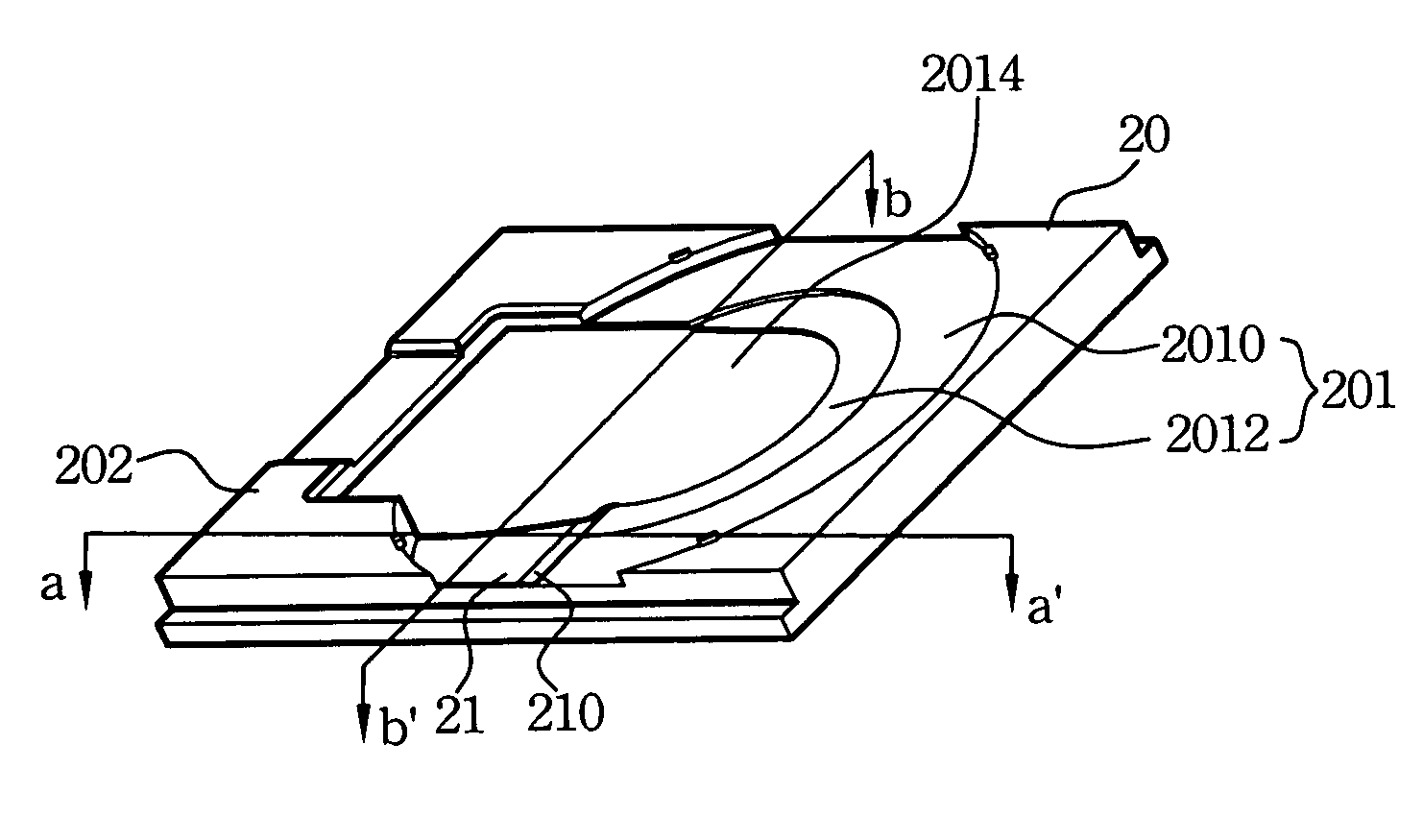
[0020]The present invention provides a heat-dissipating structure of a tray applied to a disc drive, that can lead airflow produced by a rotated disc into a descent part of the tray. Airflow between the tray and the disc is thus moved downward so as to increase the flowing speed and the flowing quantity of the airflow flowing through an optical pickup unit (OPU), and then improve the heat-dissipating ability of the electronic element in the disc drive.

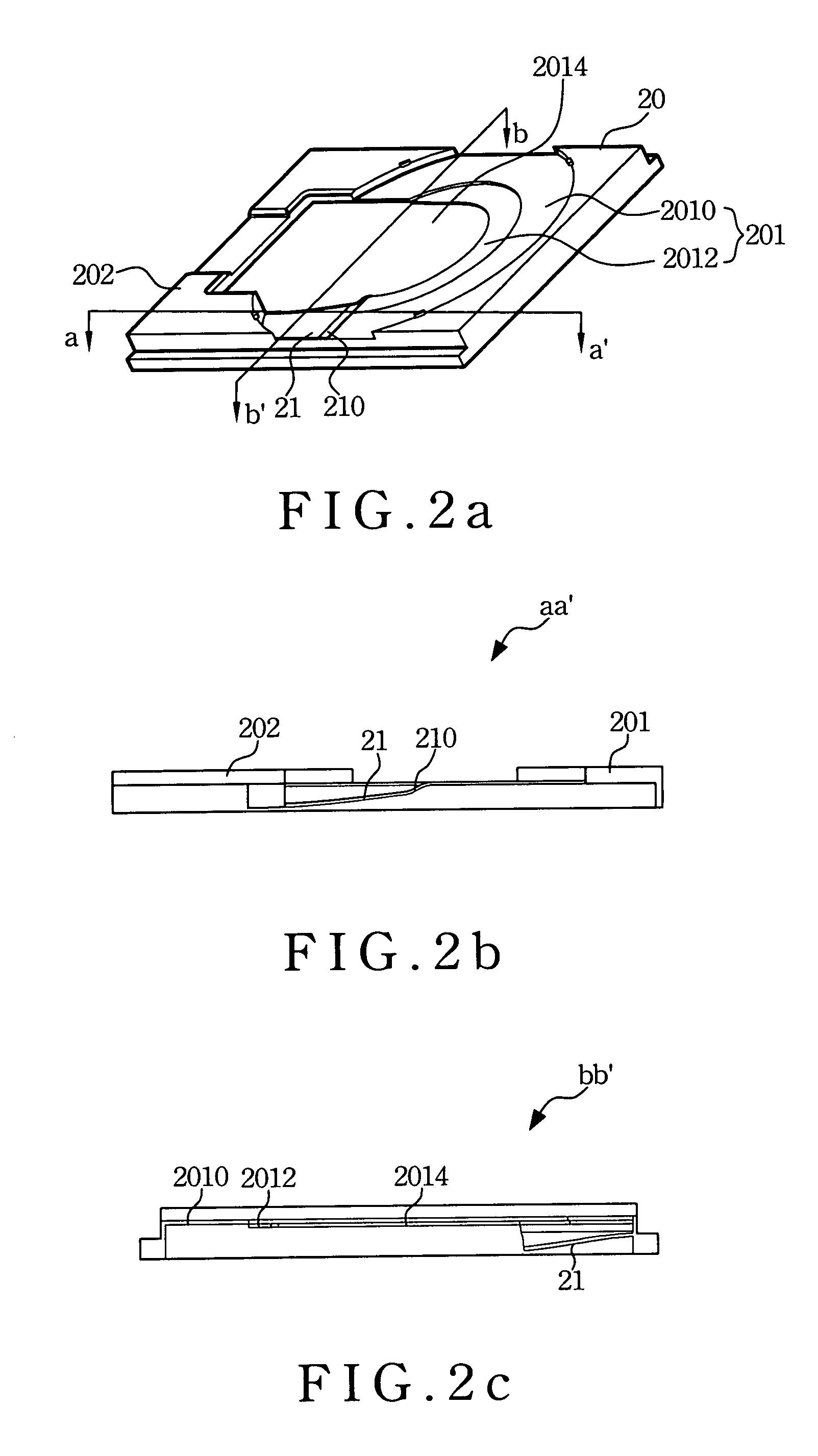
[0021]Please refer to FIGS. 2a to 2c, which illustrate a schematic view of a first embodiment of a heat-dissipating structure of a disc drive of the present invention, a schematic cross sectional view of a line aa′ of FIG. 2a, and a schematic cross sectional view of a line bb′ of FIG. 2a. The heat-dissipating structure of the present invention comprises a tray 20 and a diversion plate 21. The tray 20 is movably mounted on the disc drive for loading a disc. The tray 20 comprises a body 201 having a first concavity loading surface 2010, ...


PUM

PropertyMeasurementUnit
heat-dissipatingaaaaaaaaaa
heat-aaaaaaaaaa
sizeaaaaaaaaaa

Abstract

A heat-dissipating structure of a disc drive comprises a tray and a diversion plate. The tray has a body with a concavity loading surface for loading a disc to be in and out the disc drive, and the loading surface has a central hole. Further the diversion plate is disposed on one side of the loading surface, and connected to the loading surface, wherein the diversion plate extends downward and slopes from the connection of the diversion plate and the loading surface.

Description

FIELD OF THE INVENTION[0001]The present invention relates to a heat-dissipating structure of a disc drive, more particularly to a heat-dissipating structure of a tray for promoting the cooling function of an optical pickup unit (OPU).BACKGROUND OF THE INVENTION[0002]Due to the limited size in the half-height disc drive, the electronic elements disposed in the disc drive are full of capacity thereof. While more functions added to the disc drive, the heat generated from the elements are continuously increased. Therefore, to consider the heat-dissipating requirements for the elements is a must, such as the heat-dissipating conditions for an optical pickup unit (OPU). Especially, in case the disc drive with the Blue-Ray System, the temperature in the Laser Diode almost closes to the upper limit of the operated temperature. Hence, to improve the heat-dissipating ability for such inside elements may be rush at the field.[0003]FIG. 1 illustrates a schematic view of a disc drive 1 based on ...

Claims


Application Information

Patent Timeline
Patent Type & Authority Patents(United States)
IPC IPC(8): G11B33/02
CPCG11B33/142G11B17/056
Inventor CHANG, NAI-WENWANG, WEN-HONGCHUANG, JUI-NANYEH, SHIH-LIN
Owner LITE ON IT
Features
  • R&D
  • Intellectual Property
  • Life Sciences
  • Materials
  • Tech Scout
  • Unparalleled Data Quality
  • Higher Quality Content
  • 60% Fewer Hallucinations
Learn More