Check patentability & draft patents in minutes with Patsnap Eureka AI!

High temperature seal for electric lamp

a current conductor and electric lamp technology, applied in the field of seals for electric lamps, can solve the problems of large heat generation of electric lamps, reduced service life of lamps, and molybdenum foil

Inactive Publication Date: 2010-07-20
GENERAL ELECTRIC CO
View PDF21 Cites 5 Cited by
  • Summary
  • Abstract
  • Description
  • Claims
  • Application Information

AI Technical Summary

Benefits of technology

The coating significantly extends the lifespan of the lamp by reducing oxidation rates, allowing the lamp to withstand higher thermal loads without forced cooling, thus minimizing noise and enabling more compact designs.

Problems solved by technology

During lamp operation, the pinch point and foil are exposed to thermal stresses that can crack the seal or oxidize the foil and leads, which reduce the service life of the lamp.
The light produced by electric lamps creates large quantities of heat, thereby exposing the molybdenum foil and leads in the pinch point to elevated temperatures.
Consequently, oxidation of the molybdenum can cause the thickness of the foil to increase and eventually crack the pinch seal, thus ending the service life of the lamp.
Force cooling may include the use of positive displacement fans, which increase the overall fixture (luminaire) noise levels.
This excess noise is undesirable in various applications, including the entertainment, sports, studio and news industries.

Method used


Image

  • High temperature seal for electric lamp
  • High temperature seal for electric lamp

Examples


example 1

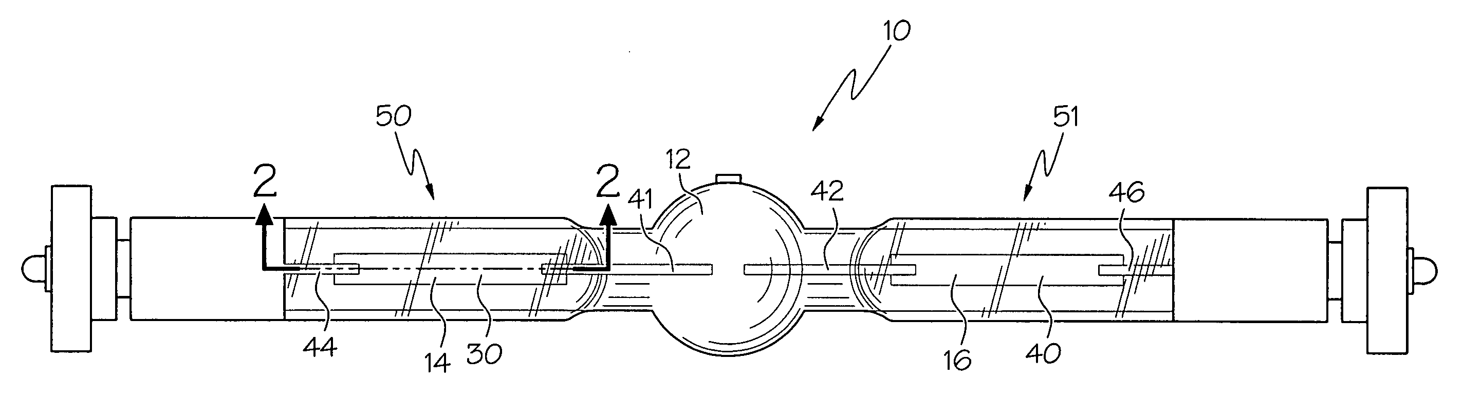
[0028]A total of 43 outer leads connected to molybdenum foils were coated with the invented coating via magnetron sputtering in a vacuum chamber. A Hauzer Sputtering System coater was used to apply the first layer and topcoat layer. The coating was applied substantially as shown in FIG. 2. Approximately only the first 5-6 mm of the foil, where the foil and outer lead are connected, was coated. FIG. 2 shows a representative portion of the 43 outer leads and foils that were coated. The remaining portion of the foil was not coated. The 43 outer leads and foils were coated with two layers of chromium, wherein 18 were coated with both layers applied under the same process parameters (set 1) and 25 were coated with each layer applied under separate, semi-similar process parameters (set 1 & 2). The vacuum seal of the deposition chamber was never broken as the 43 outer leads and foils were coated with both layers. The process parameter sets used during the coating of the 43 outer leads and ...

example 2

[0035]In another experiment, outer leads connected to molybdenum foils were coated with the invented coating via sputtering in a vacuum chamber. A Leybold Dynamet 4V Sputtering System coater was used to apply the first layer and topcoat layer. Again, approximately the first 5-6 mm of the foil, where the foil and outer lead are connected, was coated. The remaining portion of the foil was not coated. The outer leads and foils were coated with two layers, the first layer being silver and the topcoat layer being hydrogenated silicon oxy carbon polymer (SiOxHyCz), being Wacker Silicone Fluid AK 0.65 (99%+HMDSO, <0.5 ppm Cl) supplied by Wacker Chemical Corporation, Adrian, Mich. As seen below in Table 4, the coating of the first layer and the topcoat layer involved a pre-treatment or ramping-up process and a coating process, wherein the pre-treatment or ramping-up and coating process parameters are dissimilar. The pre-treatment portion associated with the first layer was for outer lead an...


PUM

PropertyMeasurementUnit
thickaaaaaaaaaa
pressureaaaaaaaaaa
thickaaaaaaaaaa

Abstract

An improved seal for an electric lamp is provided. An oxidation-resistant coating is provided on the current conductor where the outer lead joins the seal foil, preferably at the pinch seal. The coating is preferably a chromium layer covered by a chromium layer or a silver layer covered by a layer of hydrogenated silicon oxy carbon polymer. The coating is preferably applied via sputtering where the coating is subject to high energy electron or ion bombardment during sputtering. Preferably the coating is applied via sputtering at increased deposition pressure.

Description

FIELD OF THE INVENTION[0001]The invention relates generally to electric lamps and more particularly to a seal for a current conductor for an electric lamp.DESCRIPTION OF RELATED ART[0002]Electric lamps are equipped with current conductors to conduct the supply current required to operate the lamp. The current conductor often includes an outer lead, a seal foil and an inner lead (e.g. electrode, filament). The outer lead enters the lamp and is connected or welded to the foil, which is commonly composed of molybdenum. The foil is often a thin, rectangular piece of molybdenum with edges that typically taper at the ends. The foil and leads are pinched or sealed or fused at the ends of the lamp envelope (i.e. pinch point) in a vacuum-tight manner so that the internal chamber of the lamp is effectively a sealed volume. During lamp operation, the pinch point and foil are exposed to thermal stresses that can crack the seal or oxidize the foil and leads, which reduce the service life of the ...

Claims


Application Information

Patent Timeline
Patent Type & Authority Patents(United States)
IPC IPC(8): H01J17/18
CPCH01J9/326H01J61/36
Inventor CHOWDHURY, ASHFAQUL ISLAMHUME, ROGERPRESTON, BARRYISRAEL, RAJASINGHZHAO, TIANJI
Owner GENERAL ELECTRIC CO
Features
  • R&D
  • Intellectual Property
  • Life Sciences
  • Materials
  • Tech Scout
  • Unparalleled Data Quality
  • Higher Quality Content
  • 60% Fewer Hallucinations
Learn More