Check patentability & draft patents in minutes with Patsnap Eureka AI!

Asymmetric rise/fall time and duty cycle control circuit

a control circuit and rise/fall time technology, applied in pulse manipulation, pulse technique, instruments, etc., can solve problems such as signal distortion, significant increase in settling time, and potential for jitter

Active Publication Date: 2010-07-27
II VI DELAWARE INC
View PDF9 Cites 5 Cited by
  • Summary
  • Abstract
  • Description
  • Claims
  • Application Information

AI Technical Summary

Benefits of technology

The solution effectively compensates for asymmetric rise / fall times and duty cycle deviations, improving signal quality and reducing jitter, thereby enhancing the performance and reliability of high-speed data transmission networks.

Problems solved by technology

However, due to inherent non-linearity in most lasers, the rise time as measured on the eye diagram is faster than the fall time or the fall time is faster than the rise time.
This asymmetric rise / fall time often causes signal distortion to occur.
If the optical intensity undershoots too far, the laser may even turn off thereby significantly increasing the settling time.
Once again, settling time is increased thereby introducing the potential for jitter.
The overshoot and undershoot problems discussed above may also have other undesirable effects.
For example, before the electrical signal is converted into the optical signal, the existence of overshoot and undershoot may cause the emission of electromagnetic interference, thereby potentially adversely affecting the performance of the telecommunications system as a whole.
However, due to the asymmetric rise / fall time discussed previously and other factors, the output signal often does not exhibit a 50% duty cycle.
Such duty cycle distortion often leads to signal distortion.

Method used


Image

  • Asymmetric rise/fall time and duty cycle control circuit
  • Asymmetric rise/fall time and duty cycle control circuit
  • Asymmetric rise/fall time and duty cycle control circuit

Examples


Embodiment Construction

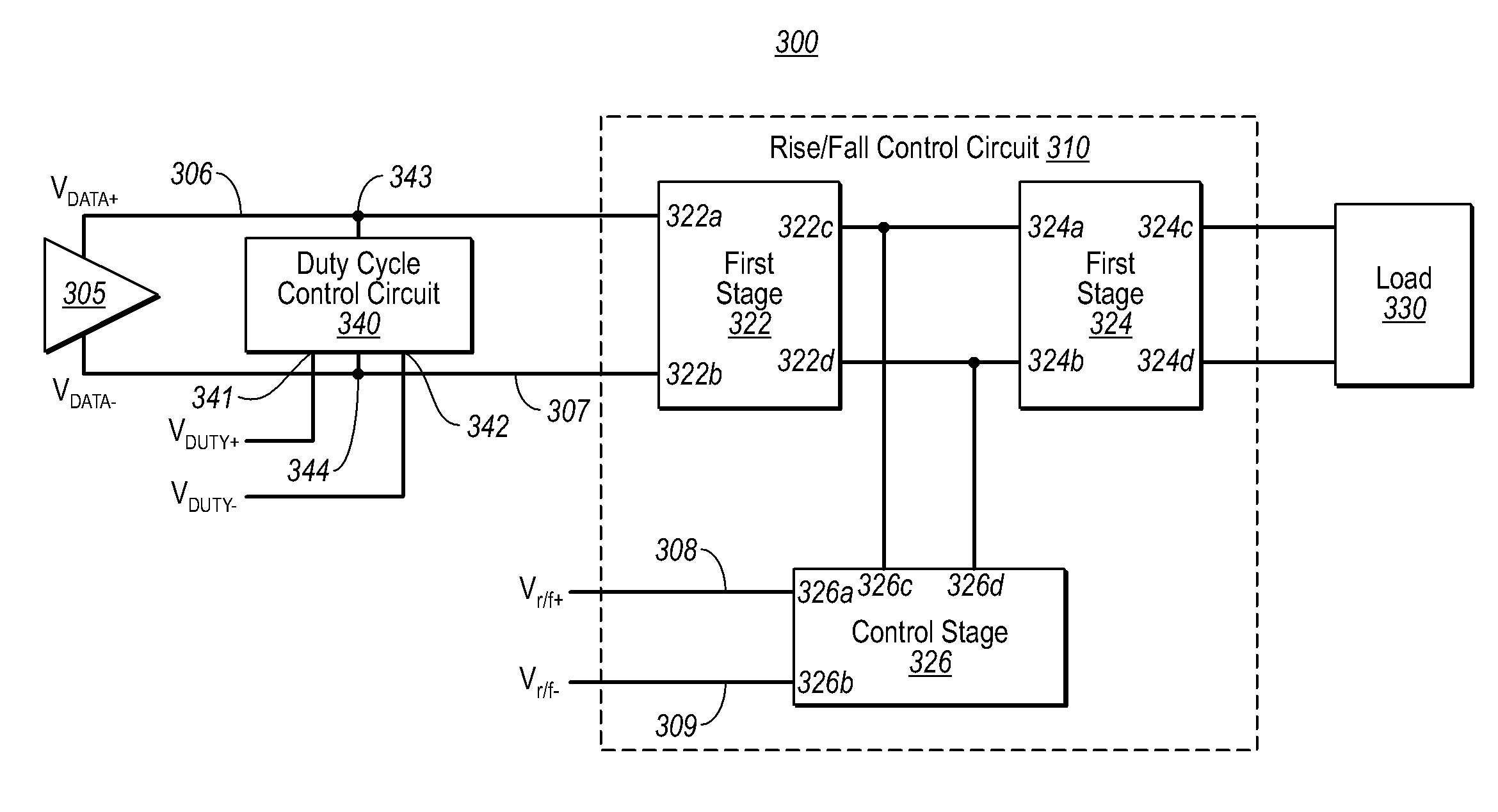
[0024]Embodiments disclosed herein relate to modules and signal control circuits configured to at least partially compensate or adjust for asymmetric rise / fall time. The circuit may include a first input node configured to receive a first data signal and a second input node configured to receive a second data signal that is complementary of the first data signal.

[0025]The circuit may also include a first stage having a first node coupled to the first input node and a second node coupled to the second input node and a second stage having a first node coupled to a third node of the first stage and a second node coupled to a fourth node of the first stage. The second stage may be configured to drive a load such as a laser.

[0026]The circuit may further include a third input node configured to receive a third data signal and a fourth input node configured to receive a fourth data signal that is the complementary of the third data signal. Additionally, a control stage having a first node ...


PUM


Abstract

Modules and signal control circuits configured to at least partially compensate for or adjust for asymmetric rise / fall time. The circuit may include a first input node configured to receive a first data signal and a second input node configured to receive a second data signal that is complementary of the first data signal. The circuit may also include a first stage having a first node coupled to the first input node and a second node coupled to the second input node and a second stage having a first node coupled to a third node of the first stage and a second node coupled to a fourth node of the first stage. The second stage may be configured to drive a load such as a laser. The circuit may further include a third input node configured to receive a third data signal and a fourth input node configured to receive a fourth data signal that is the complementary of the third data signal. Additionally, a control stage having a first node coupled the third input node, having a second node coupled to the fourth input node, having a third node coupled to the third node of the first stage and having a fourth node coupled to the fourth node of the first stage.

Description

CROSS-REFERENCE TO RELATED APPLICATIONS[0001]This application claims the benefit of U.S. Provisional Application No. 60 / 827,239, filed Sep. 28, 2006, which is incorporated herein by reference in its entirety.BACKGROUND[0002]Computing and networking technology have transformed our world. As the amount of information communicated over networks has increased, high speed transmission has become ever more critical. Many high speed data transmission networks rely on optical transceivers and similar devices for facilitating transmission and reception of digital data embodied in the form of optical signals over optical fibers. Optical networks are thus found in a wide variety of high speed applications ranging from as modest as a small Local Area Network (LAN) to as grandiose as the backbone of the Internet.[0003]Typically, data transmission in such networks is implemented by way of an optical transmitter (also referred to as an electro-optic transducer), such as a laser or Light Emitting D...

Claims


Application Information

Patent Timeline
Patent Type & Authority Patents(United States)
IPC IPC(8): H04B10/00
CPCH03F3/45085H03F3/45475H03K5/1565H03F2203/45134H03F2203/45324H03F2203/45566H03F2203/45631H03F2203/45641H03F2203/45654
Inventor NGUYEN, THE'LINHMORAN, TIMOTHY G.
Owner II VI DELAWARE INC
Features
  • R&D
  • Intellectual Property
  • Life Sciences
  • Materials
  • Tech Scout
  • Unparalleled Data Quality
  • Higher Quality Content
  • 60% Fewer Hallucinations
Learn More