Check patentability & draft patents in minutes with Patsnap Eureka AI!

Air flow nozzle for air flow meter

a technology of air flow meter and air flow nozzle, which is applied in the direction of suspension and porous material analysis, instruments, and material analysis, can solve the problems of foam that fails to meet acceptable quality standards, foam is rendered unusable, and no known solution to reliably solve, etc., and achieves the effect of easy insertion into the foam

Inactive Publication Date: 2010-08-03
INT BUSINESS MASCH CORP
View PDF5 Cites 0 Cited by
  • Summary
  • Abstract
  • Description
  • Claims
  • Application Information

AI Technical Summary

Benefits of technology

This method provides a reliable, repeatable, and objective assessment of bead fusion quality without damaging the foam, enabling consistent testing and maintaining its usability for protecting fragile items.

Problems solved by technology

Variations in these characteristics may cause the foam to fail acceptable quality standards, because foam that falls outside acceptable quality standards may not, for example, adequately protect products from damage when the foam is placed around these products.
As a result, the foam is rendered unusable.
Currently, no known solutions exist to reliably and repeatedly test the quality of fused beads in a foam without destroying the foam.

Method used


Image

  • Air flow nozzle for air flow meter
  • Air flow nozzle for air flow meter
  • Air flow nozzle for air flow meter

Examples


Embodiment Construction

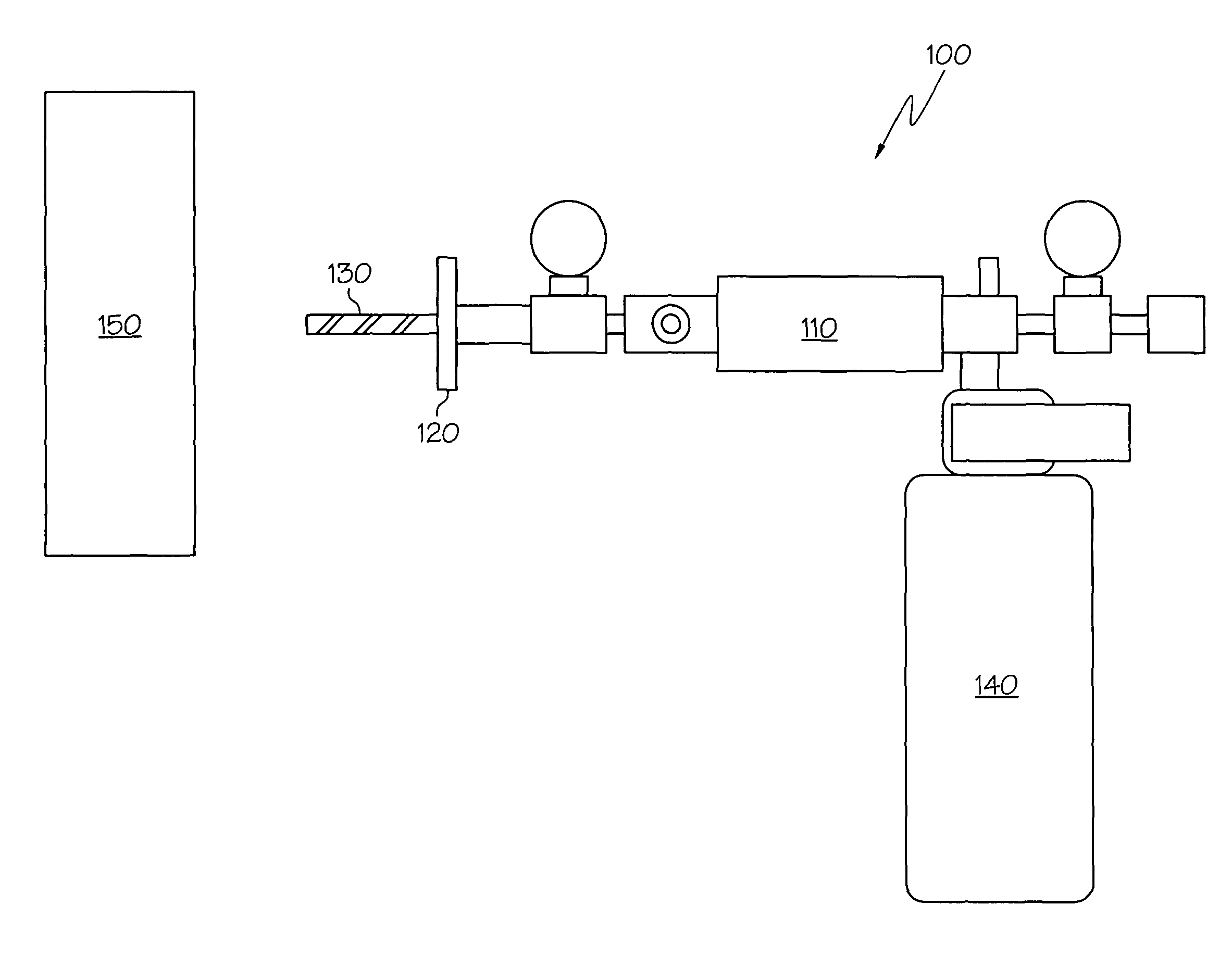
[0015]FIG. 1 shows a device for measuring the flow of air in foam, in accordance with an illustrative embodiment of the present invention. Device 100 includes air flow meter 110, nozzle 130, and member having a substantially planar surface 120. Nozzle 130 and member 120 are operatively connected to air flow meter 110, and member 120 is operatively connected to nozzle 130. The term “operatively connected” means that components that are operatively connected to each other are connected and are in an operative or working condition in relation to each other. Components are connected if they are directly or indirectly connected to each other. Components are directly connected if each component is directly touching the other. First and second components are indirectly connected if other components are also connected to the first and second components, though the first and second components do not directly connect. In this case, nozzle 130 is directly and operatively connected to member 12...


PUM

PropertyMeasurementUnit
diameteraaaaaaaaaa
diameteraaaaaaaaaa
diameteraaaaaaaaaa

Abstract

The aspects of the present invention provide for an apparatus for conveying air into foam so that the flow of air within the foam may be monitored to determine one or more characteristics of the foam. The apparatus includes a nozzle and a member having a substantially planar surface. The nozzle includes a tube sized and dimensioned to be inserted easily into the foam. The tube has a wall and an aperture formed in the wall. The aperture is sized and dimensioned to allow air to flow through the aperture and into the foam, and the aperture extends partially about the circumference of the tube. The member is mounted to the nozzle and is also connected to an air flow meter.

Description

BACKGROUND OF THE INVENTION[0001]1. Field of the Invention[0002]The aspects of the present invention relate generally to the field of molded foams.[0003]2. Description of the Related Art[0004]Molded foam is one of the most common forms of packaging material used for the shipment of fragile items. Some examples of molded foams are expandable polystyrene (EPS), expandable polypropylene (EPP), and expandable polyethylene (EPE).[0005]Molded foam is initially supplied to molders as a resin in the form of beads. The beads are loaded into a mold along with a blowing agent, such as pentane or carbon dioxide, which allow the beads to expand upon processing. Steam pressure is used to expand the beads into a shape determined by the mold and then force the beads to fuse together after expansion. The fused beads are then cooled to form a molded, closed-cell foam part.[0006]The cushioning characteristic of the foam is based on the shape of the foam, the bead size, the bead processing conditions, ...

Claims


Application Information

Patent Timeline
Patent Type & Authority Patents(United States)
IPC IPC(8): G01N15/08
CPCB29C44/60
Inventor LIVERMAN, IVAN NEILMARESH, MARK EDMUNDSATTORA, CHRISTOPHER JOHNSTEGNER, ERIC ALLENSTEGNER, ROBERT WILLIAM
Owner INT BUSINESS MASCH CORP
Features
  • R&D
  • Intellectual Property
  • Life Sciences
  • Materials
  • Tech Scout
  • Unparalleled Data Quality
  • Higher Quality Content
  • 60% Fewer Hallucinations
Learn More