Check patentability & draft patents in minutes with Patsnap Eureka AI!

Piezoelectric actuator with a gimballed valve

a technology of gimbal valve and actuator, which is applied in the direction of valve operating means/release devices, water supply installation, generator/motor, etc., can solve the problems of complex assembly, difficult manufacturing of valves in large quantities, and increase the cost of complex assembly

Inactive Publication Date: 2010-11-30
HONEYWELL INT INC
View PDF16 Cites 0 Cited by
  • Summary
  • Abstract
  • Description
  • Claims
  • Application Information

AI Technical Summary

Benefits of technology

The solution allows for precise control of fluid flow rates, simplifies manufacturing by reducing sensitivity to mechanical tolerances, and lowers production costs while maintaining accuracy in simulating in-flight pneumatic pressures.

Problems solved by technology

Due to the complexity of the assemblies and the interrelated mechanical tolerance sensitivity, the aforementioned valves are difficult to manufacture in large quantities in a short period of time.
In addition, the complex assembly increases cost.

Method used


Image

  • Piezoelectric actuator with a gimballed valve
  • Piezoelectric actuator with a gimballed valve
  • Piezoelectric actuator with a gimballed valve

Examples


Embodiment Construction

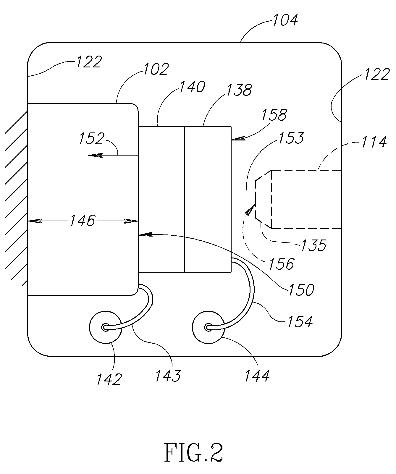
[0013]FIG. 1 shows a flow control valve 100 having a piezoelectric actuator 102 located within a chamber 104 of a valve support structure 106 according to an embodiment of the invention. The flow control valve 100 may be used to control a flow of fluid into the chamber 104. The flow control valve 100 may be employed to proportionally modulate the flow into the chamber 104 to achieve a desired output flow rate of the fluid. The flow control valve 100 further includes a first pressure fitting 108 and a second pressure fitting 110 coupled to and positioned within passages 112, 113 formed in the support structure 106. In the illustrated embodiment, an adjustable nozzle 114 is coupled to the first pressure fitting 108 and a fixed orifice 116 coupling the second pressure fitting 110 to the plenum chamber 104.

[0014]In one embodiment, the support structure 106 is a machined, one-inch (25.40 millimeters) thick plate having approximately a two-inch (50.80 millimeters) square area (width multi...


PUM


Abstract

A gimballed valve for a flow control valve operates as a sealing member for an adjustable nozzle and is coupled to a piezoelectric actuator having stacked piezoelectric members that are toroidally shaped. The gimballed valve includes at least two support rings and a center closure member. In one embodiment only an outermost support is in contact with at least one member of the piezoelectric actuator. The support rings may be concentrically arranged and coupled together with flexure members. The center closure member operates to seal against an orifice in the adjustable nozzle and may deflect upon contact with the adjustable nozzle to account for misalignment issues that may arise during machining and / or assembly of the flow control valve.

Description

PRIORITY[0001]This application is a continuation-in-part application and claims priority to U.S. patent application Ser. No. 11 / 934,000 filed on Nov. 1, 2007, the subject matter of which is incorporated herein by reference in its entirety.BACKGROUND OF THE INVENTION[0002]Flow control valves are used to control fluid flow rates in a variety of applications. One particular application relates to controlling a flow (e.g., gas or liquid) in a pneumatic test apparatus when testing various pneumatic pressure systems or components that are to be installed on an aircraft. By way of example, one type of pneumatic test apparatus is an air data tester (ADT), which is often employed in ground testing aircraft aerospace systems or components. One type of aerospace test system simulates in-flight air pressures to supply pneumatic data to an aircraft control and display avionics system, which in turn provides data regarding the aircraft's altitude, vertical speed, airspeed, Mach number, etc.[0003]...

Claims


Application Information

Patent Timeline
Patent Type & Authority Patents(United States)
IPC IPC(8): F16K31/02
CPCF16K31/007Y10T137/0318
Inventor DUPUIS, PAULVETSCH, LEE
Owner HONEYWELL INT INC
Features
  • R&D
  • Intellectual Property
  • Life Sciences
  • Materials
  • Tech Scout
  • Unparalleled Data Quality
  • Higher Quality Content
  • 60% Fewer Hallucinations
Learn More