Check patentability & draft patents in minutes with Patsnap Eureka AI!

Light distribution control method, light distribution control device, and greenhouse using the same

a control device and light distribution technology, applied in the field of passive daylighting, can solve the problems of large portion of light loss, insufficient symmetry of diffused rays with respect to a light incident at a large azimuth angle, and difficulty in stably realizing shape and function, etc., and achieve the effect of efficient utilization of diffused ligh

Inactive Publication Date: 2010-11-30
S T I JAPAN
View PDF17 Cites 8 Cited by
  • Summary
  • Abstract
  • Description
  • Claims
  • Application Information

AI Technical Summary

Benefits of technology

The solution enhances light diffusion symmetry and energy use efficiency by directing light in a desirable manner, improving luminance distribution and reducing light loss, without the need for advanced manufacturing technologies.

Problems solved by technology

However, the array of the ridges required for such a blind and light distribution control device demands a high level of manufacturing technology, so that it is not easy to stably realize the shape and the function satisfied on a stable basis.
Therefore, the symmetry of diffused rays with respect to a light incident at a large azimuth angle is not sufficient.
In a case of the use of such diffused light passing through the surface of the structure, a large portion of the light is lost due to the reflection on the surface of the structure.
This results in leaving room for improvement of energy use efficiency.

Method used


Image

  • Light distribution control method, light distribution control device, and greenhouse using the same
  • Light distribution control method, light distribution control device, and greenhouse using the same
  • Light distribution control method, light distribution control device, and greenhouse using the same

Examples


embodiment 1

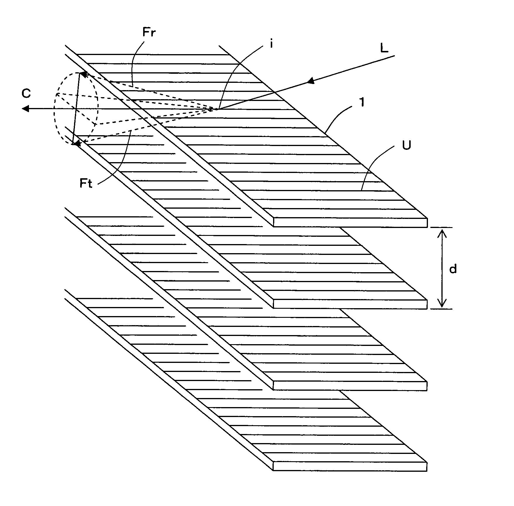
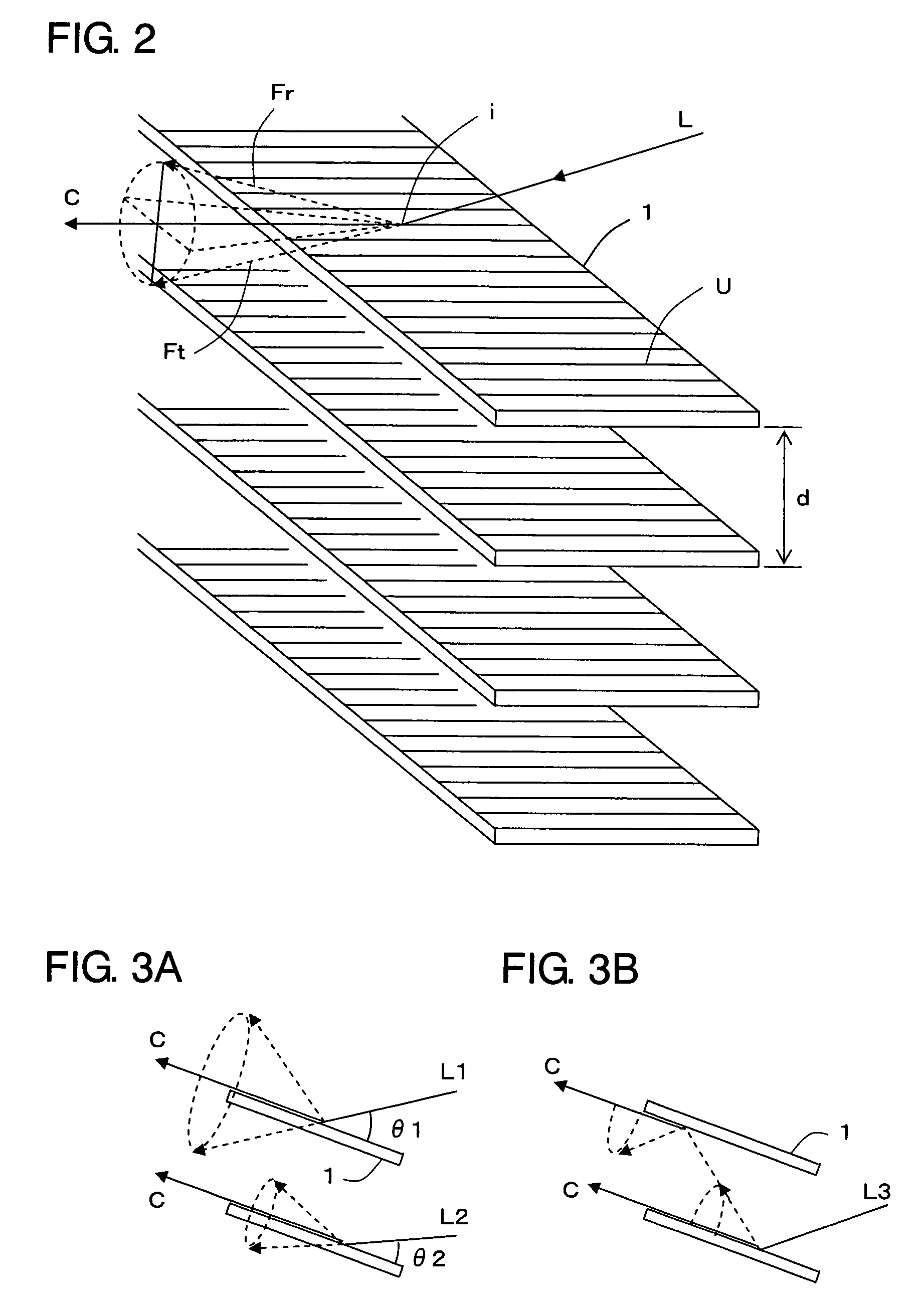
[0046]A light distribution control device according to Embodiment 1 is shown in FIG. 2. The light distribution control device comprises a plurality of structures 1, each of which has a number of ridges U as described above and is formed in a long and thin plate shape or a long and thin film shape. In each of the structures 1, the ridges U are formed so as to cross a longitudinal direction of each of the structures 1, more specifically, to be orthogonal thereto. The structures 1 are arrayed such that the corresponding faces of the adjacent structures 1 are parallel to each other and apart from each other at a predetermined distance as well as the ridges U of the adjacent structures 1 are parallel to each other. In FIG. 2, the ridges U are schematically expressed by simple line segments in order to indicate the direction of formation thereof. In fact, the ridges U, each of which has the cross section forming a portion of a substantial circle and the surface being practically specular,...

embodiment 2

[0054]FIG. 6 shows a light distribution control device according to Embodiment 2. This light distribution control device has almost the same structure as the light distribution control device according to Embodiment 1 but further includes an adjusting mechanism 2 for adjusting an angle of the plurality of structures 1 which are parallel to one another. A mechanism for adjusting a tilt of a plurality of blades of a general-purpose blind can be used as the adjusting mechanism 2.

[0055]Since the adjusting mechanism 2 is provided, the angle of the respective structures 1 can be easily adjusted corresponding to the desired direction for light distribution.

embodiment 3

[0056]While each of the structures 1 used in the light distribution control device according to Embodiment 1 has a plate shape, it is possible to use a structure 1 whose cross section that is orthogonal to a longitudinal direction thereof has a bent shape or a V-shape as shown in FIG. 7. That is, the structure 1 comprises an outside portion 3 and an inside portion 4 which are divided along the longitudinal direction, wherein the ridges U are formed on each of the surface 3a of the outside portion 3 and the surface 4a of the inside portion 4 in a direction orthogonal to the longitudinal direction. The structure 1 has both optical transparency and optical reflectivity.

[0057]As shown in FIG. 8, a plurality of structures 1, each of whose cross section has a bent shape, are arrayed in parallel and apart from each other at a predetermined distance to construct the light distribution control device according to Embodiment 3.

[0058]For example, the light distribution control device is placed...


PUM


Abstract

A plurality of structures each having a number of ridges and being formed in a long and thin plate shape or a long and thin film shape. The cross section of each of the ridges forms a portion of a substantial circle and a surface thereof is a practically specular surface. The ridges of each structure are parallel to each other and respective adjacent surfaces thereof correspond to each other in parallel and are spaced apart from each other at a predetermined distance. When light is incident on a point of a surface of one of the structures at an incident angle, in either its reflection or transmittance, the light is diffused in a circular conical plane whose vertex is the incident point and whose center axis is a line parallel to the ridges, by a diffraction effect caused by the arrayed ridges. The flux of reflected diffused light is spread in one lengthwise half of the circular conical plane and the flux of transmitted diffused light is spread in the other lengthwise half of the circular conical plane.

Description

BACKGROUND OF THE INVENTION[0001]1. Field of the Invention[0002]The present invention relates to a passive daylighting technology or a technology for controlling a flux of an artificial light source without using a driving means.[0003]2. Description of the Related Art[0004]A venetian blind disclosed in JP 2002-081275A by the applicant of the present invention provides a structure wherein each of transparent slats is divided into two portions, i.e. an outdoor side and an indoor side. Also, a number of ridges, each of which has substantially circular cross section, are arrayed sufficiently / substantially close to each other in a direction perpendicular to the longitudinal axis of the slat on the upper surface of the outdoor side of the slat. The sunlight reflected on this surface is diffused substantially symmetrically by the ridges with respect to an axis parallel to a longitudinal direction of each of the ridges, then strikes the lower surface of the indoor side of the slat just abov...

Claims


Application Information

Patent Timeline
Patent Type & Authority Patents(United States)
IPC IPC(8): G02B27/00A01G9/22
CPCA01G9/22A01G9/243F21S11/00G02B5/0215G02B5/0221G02B5/0278G02B5/0284E06B9/24G02B5/18Y02P60/12Y02A40/25
Inventor OYAMA, NOBUO
Owner S T I JAPAN
Features
  • R&D
  • Intellectual Property
  • Life Sciences
  • Materials
  • Tech Scout
  • Unparalleled Data Quality
  • Higher Quality Content
  • 60% Fewer Hallucinations
Learn More