Check patentability & draft patents in minutes with Patsnap Eureka AI!

Circuit and method for controlling the secondary FET of transformer coupled synchronous rectified flyback converter

a technology of synchronous rectified flyback converter and transformer, which is applied in the field of power electronics, can solve the problems of otherwise and achieve the effect of avoiding false triggering and increasing the secondary power loss of the tcs

Active Publication Date: 2011-01-25
ALPHA & OMEGA SEMICON INC
View PDF6 Cites 6 Cited by
  • Summary
  • Abstract
  • Description
  • Claims
  • Application Information

AI Technical Summary

Benefits of technology

[0020]As a result, the secondary FET control circuit avoids false triggering of the FETsc by the numerous undesirable Vsec ringings and entry into incorrect states around the time marks tPSX and tSLC resulting in an otherwise increased secondary power loss of the TCSC.
[0026]In a more specific embodiment, the VSD sense trigger, the Vsec sense trigger and the MTGD are co-packaged with the FETsc so as to form a 4-terminal replacement device for the FETsc with further increased noise immunity against false triggering of the FETsc. The 4-terminal replacement device can be deployed to locate at either the high-side or the low-side of the STC.
[0032]As a result, the method avoids false triggering of the FETsc by the numerous undesirable Vsec ringings and entry into incorrect states around the time marks tPSX and tSIC resulting in an otherwise increased secondary power loss of the TCSC.

Problems solved by technology

As a result, the secondary FET control circuit avoids false triggering of the FETsc by the numerous undesirable Vsec ringings and entry into incorrect states around the time marks tPSX and tSLC resulting in an otherwise increased secondary power loss of the TCSC.

Method used


Image

  • Circuit and method for controlling the secondary FET of transformer coupled synchronous rectified flyback converter
  • Circuit and method for controlling the secondary FET of transformer coupled synchronous rectified flyback converter
  • Circuit and method for controlling the secondary FET of transformer coupled synchronous rectified flyback converter

Examples


Embodiment Construction

[0043]The description above and below plus the drawings contained herein merely focus on one or more currently preferred embodiments of the present invention and also describe some exemplary optional features and / or alternative embodiments. The description and drawings are presented for the purpose of illustration and, as such, are not limitations of the present invention. Thus, those of ordinary skill in the art would readily recognize variations, modifications, and alternatives. Such variations, modifications and alternatives should be understood to be also within the scope of the present invention.

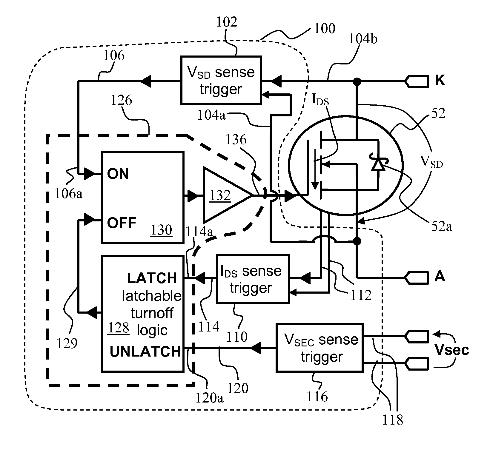
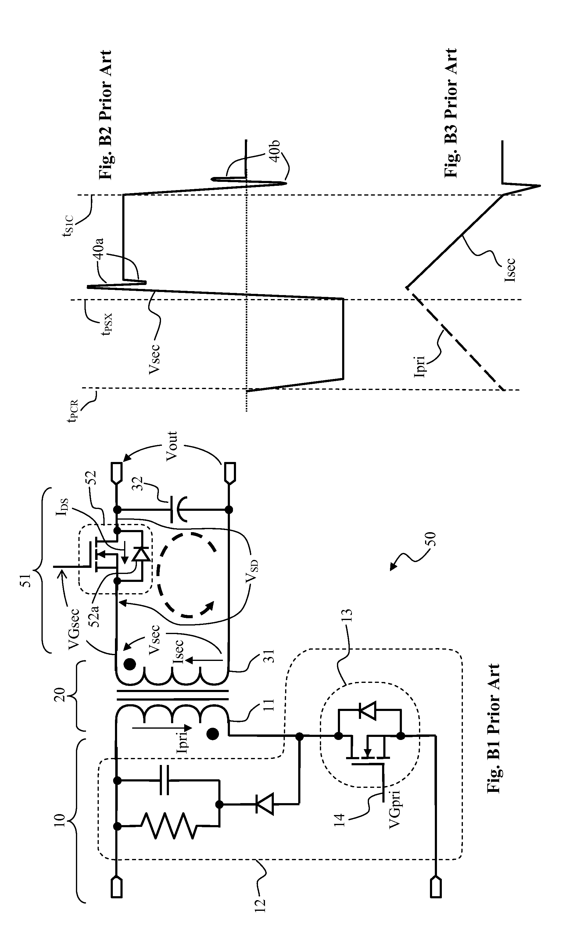
[0044]FIG. 1A and FIG. 1B illustrate the present invention FETsc control circuit 100 for controlling the secondary switching FETsc 52 in a TCSC (see FIG. B1). Recall that the secondary circuit 51 has a serial connection of a secondary transformer coil STC 31 with a secondary coil voltage Vsec, an output capacitor Cout 32 and the FETsc 52. The FETsc 52 has a built-in parasitic body diode...


PUM


Abstract

A secondary FETsc control circuit is disclosed for controlling FETsc of transformer coupled synchronous rectified flyback converter (TCSC). The control circuit includes source-drain voltage VSD sense trigger with output VSD-trigger activated upon positive 0-crossing of VSD. Drain-source current IDS sense trigger with output IDS-trigger activated upon positive 0-crossing of IDS. Secondary coil voltage Vsec sense trigger with output Vsec-trigger activated upon sensing negative Vsec. A multi-trigger gate driver (MTGD) has trigger inputs coupled to VSD-trigger, IDS-trigger, Vsec-trigger and drive output driving the FETsc gate. The MTGD has logic states of state-I where FETsc is turned off and latched, state-II where FETsc is turned off but unlatched, state-III where FETsc is turned on but unlatched. The MTGD is configured to enter state-III upon VSD-trigger, enter state-I upon IDS-trigger and enter state-IT upon Vsec-trigger. The control circuit thus avoids false triggering of the FETsc by numerous undesirable Vsec ringings.

Description

CROSS REFERENCE TO RELATED APPLICATIONS[0001]1. Field of Invention[0002]This invention relates generally to the field of power electronics. More specifically, the present invention is directed to precise control of a switching metal oxide semiconductor field effect transistor (MOSFET) on the secondary side of a flyback converter.[0003]2. Background of the Invention[0004]The usage of switched power converters has become ubiquitous in the electronics industry. A few examples are switching power supplies, DC-DC voltage converters and DC-AC voltage converters.[0005]FIG. A1 through FIG. A4 illustrate a prior art transformer coupled conventional rectified flyback converter (TCCC) 1 with a primary circuit 10 and a secondary circuit 30 magnetically coupled through a coupling transformer 20 having a primary transformer coil (PTC) 11 and a secondary transformer coil (STC) 31. The primary circuit 10 has a primary switching network (PSN) 12 with internal cyclic active switching by a primary swi...

Claims


Application Information

Patent Timeline
Patent Type & Authority Patents(United States)
IPC IPC(8): H02M3/335
CPCH02M3/33592Y02B70/1475Y02B70/10
Inventor HAVANUR, SANJAY
Owner ALPHA & OMEGA SEMICON INC
Features
  • R&D
  • Intellectual Property
  • Life Sciences
  • Materials
  • Tech Scout
  • Unparalleled Data Quality
  • Higher Quality Content
  • 60% Fewer Hallucinations
Learn More