Check patentability & draft patents in minutes with Patsnap Eureka AI!

Blade drive device and optical device

a technology of optical devices and blades, applied in the direction of camera diaphragms, shutters, instruments, etc., can solve the problems of reducing the accuracy of blade positioning, suppressing the increase in blade size,

Inactive Publication Date: 2011-02-22
SEIKO PRECISION CO LTD
View PDF4 Cites 0 Cited by
  • Summary
  • Abstract
  • Description
  • Claims
  • Application Information

AI Technical Summary

Benefits of technology

The solution enhances the positional accuracy of the blade while reducing the device's size and part count, allowing for efficient control of the aperture without the need for additional gears, thus improving control accuracy and minimizing costs.

Problems solved by technology

There is a problem in which the blade drive device is increased in size due to the presence of such gear for reducing the speed.

Method used


Image

  • Blade drive device and optical device
  • Blade drive device and optical device
  • Blade drive device and optical device

Examples


Embodiment Construction

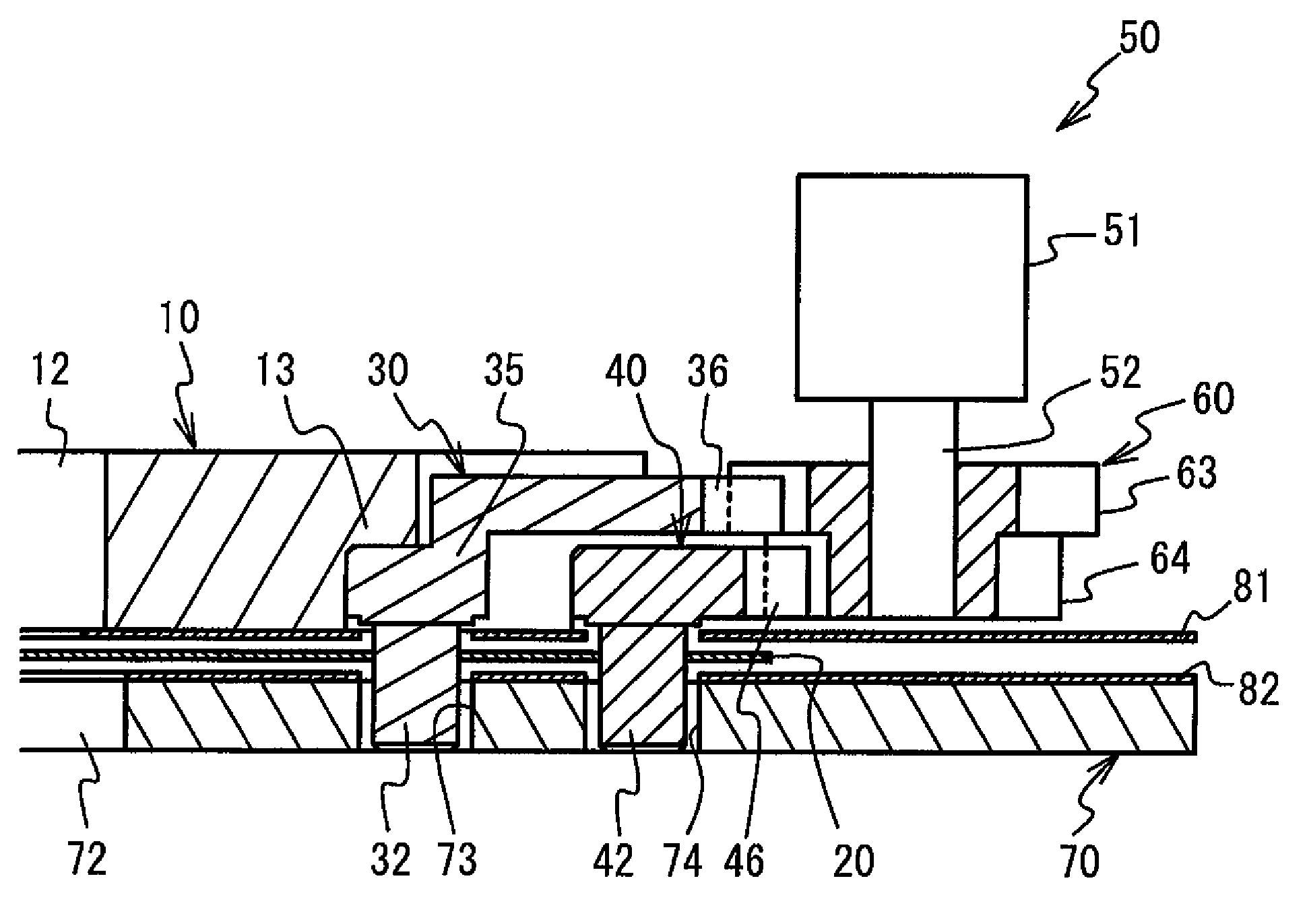
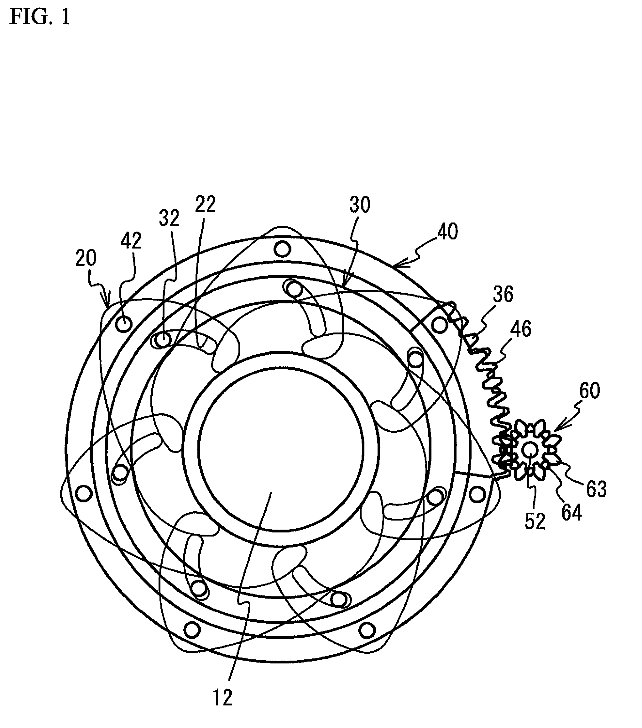
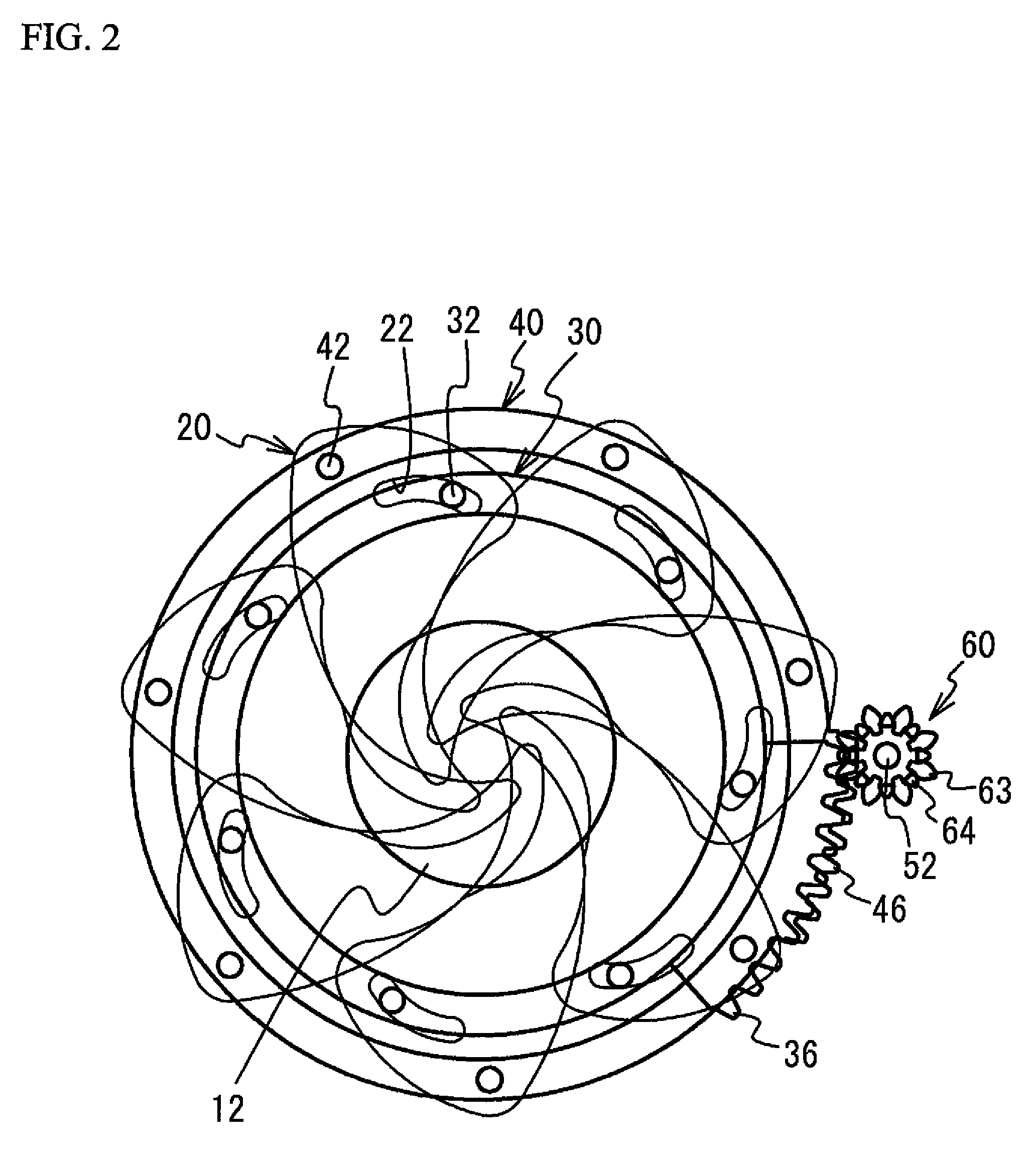
A description will now be given, with reference to the accompanying drawings, an embodiment of the present invention. FIG. 1 is a perspective view of a blade drive device in a fully opened state, FIG. 2 is a perspective view of the blade drive device in a small aperture state, and FIG. 3 is a partially cross-sectional view of the blade drive device.

Referring to FIGS. 1 to 3, the blade drive device according to the present embodiment includes: a board 10 having an opening 12 at its center portion; plural blades 20 adjusting the opening amount of the opening 12; drive rings 30 and 40 rotatably supported on the board 10 and transmitting a drive force to the plural blades 20; an electromagnetic actuator 50 serving as a drive source; a pinion gear 60; and a blade retaining board 70 having an opening 72. The drive rings 30 and 40 respectively serve as first and second drive rings.

The board 10, the blades 20, the drive rings 30 and 40, the pinion gear 60, and the blade retaining board 70 a...


PUM


Abstract

A blade drive device includes: a board having an opening; a blade for adjusting an amount of the opening; and first and second drive rings having a support structure for commonly supporting the blade for swinging, rotating in an identical direction with a given speed difference, and being arranged in a same plane.

Description

BACKGROUND OF THE INVENTION1. Field of the InventionThe present invention relates to blade drive devices and optical devices.2. Description of the Related ArtConventionally, there has been known a blade drive device having a drive ring for applying a drive force to a blade, which adjusts an opening amount of an opening formed on a board (see Japanese Examined Patent Application Publication No. 07-92580).In such a blade drive device, it is preferable to reduce and transmit the drive force from a drive source to the blade, in order to improve the positional accuracy of the blade. However, in order to reduce a speed of the drive force from the drive source, it is necessary to transmit the drive force to the drive ring via plural gears. There is a problem in which the blade drive device is increased in size due to the presence of such gear for reducing the speed.SUMMARY OF THE INVENTIONIt is therefore an object of the present invention to provide a blade drive device in which the positi...

Claims


Application Information

Patent Timeline
Patent Type & Authority Patents(United States)
IPC IPC(8): G03B9/02G03B9/08
CPCG03B9/06G03B9/02
Inventor SUZUKI, MITSURU
Owner SEIKO PRECISION CO LTD
Features
  • R&D
  • Intellectual Property
  • Life Sciences
  • Materials
  • Tech Scout
  • Unparalleled Data Quality
  • Higher Quality Content
  • 60% Fewer Hallucinations
Learn More