
RFID interrogator and RFID-interrogator control method

a technology of interrogator and interrogator, which is applied in the direction of process and machine control, testing/monitoring control system, instruments, etc., can solve the problems of complex settings, interference between the reader/writer and the electronic tag, and the interfering of the reader/writer with the other

Inactive Publication Date: 2011-03-08
FUJITSU LTD
View PDF11 Cites 8 Cited by
  • Summary
  • Abstract
  • Description
  • Claims
  • Application Information

AI Technical Summary

Problems solved by technology

If the reader / writers are communicating using radio waves of the same frequency, the reader / writers interfere with each other.
Due to this, the electronic tag is not able to receive data correctly, thus resulting in interference between the reader / writers and the electronic tag.
However, because an extent of the interference from each reader / writer must be grasped beforehand to decide a control method, complex settings need to be carried out each time a set up environment changes.

Method used


Image

  • RFID interrogator and RFID-interrogator control method
  • RFID interrogator and RFID-interrogator control method
  • RFID interrogator and RFID-interrogator control method

Examples


Embodiment Construction

[0023]Exemplary embodiments of the present invention are explained in detail below with reference to the accompanying drawings. According to the embodiments, an RFID interrogator is used as an IC tag reader / writer (hereinafter, “a reader / writer”) and electronic tags that are used as RFID responding devices are embedded in a passive type IC having a maximum communication distance of approximately several meters.

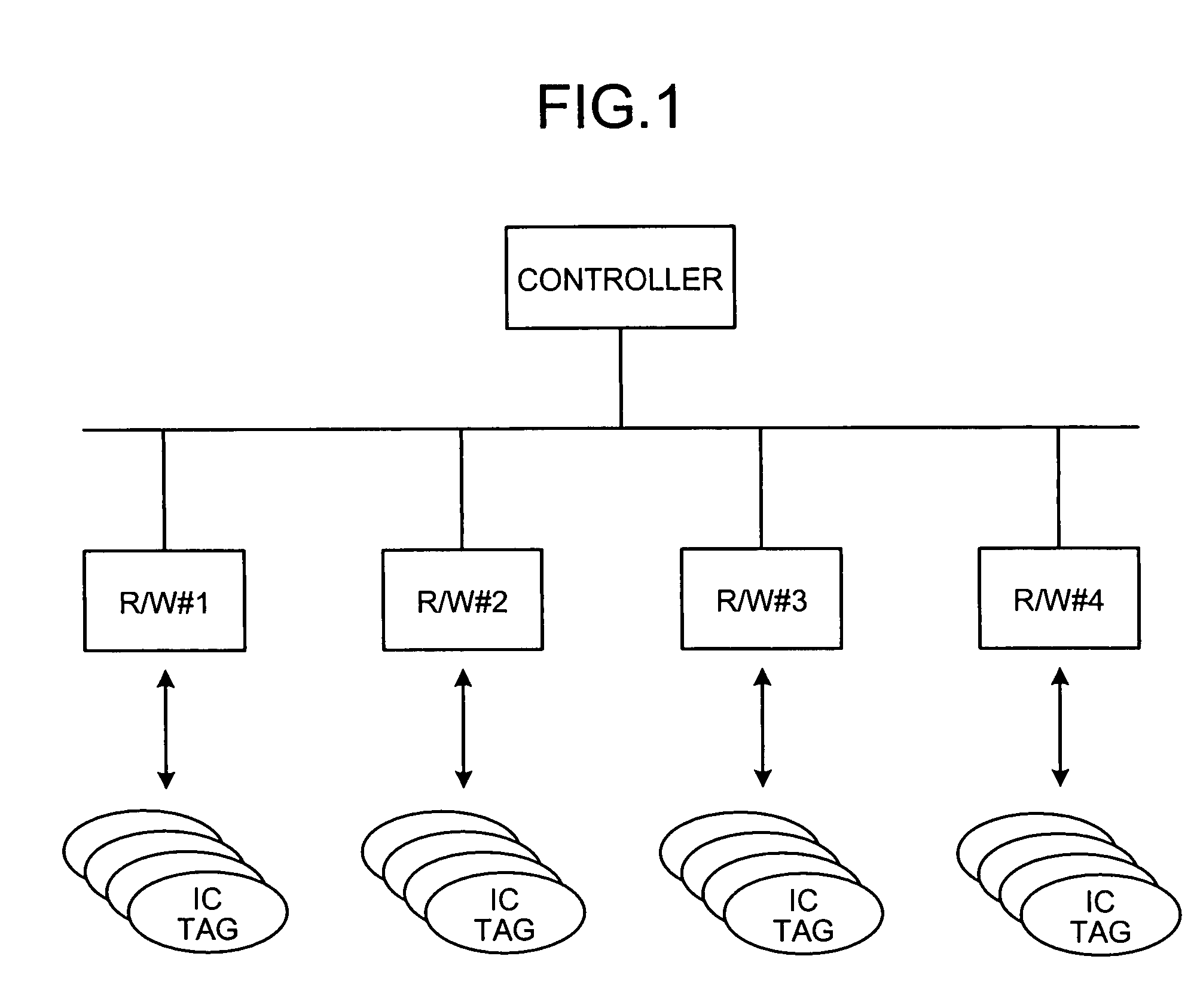
[0024]FIGS. 1 to 5 are schematics for explaining a general reader / writer based on an RFID technology that is the prerequisite of the embodiments. FIG. 1 is a schematic for explaining a control of multiple reader / writers. Each of reader / writers R / W1 to R / W4 corresponds to multiple IC tags. The reader / writers R / W1 to R / W4 communicate with the corresponding multiple IC tags. A single controller intensively controls the reader / writers R / W1 to R / W4. Thus, the multiple reader / writers can communicate with stipulated target IC.

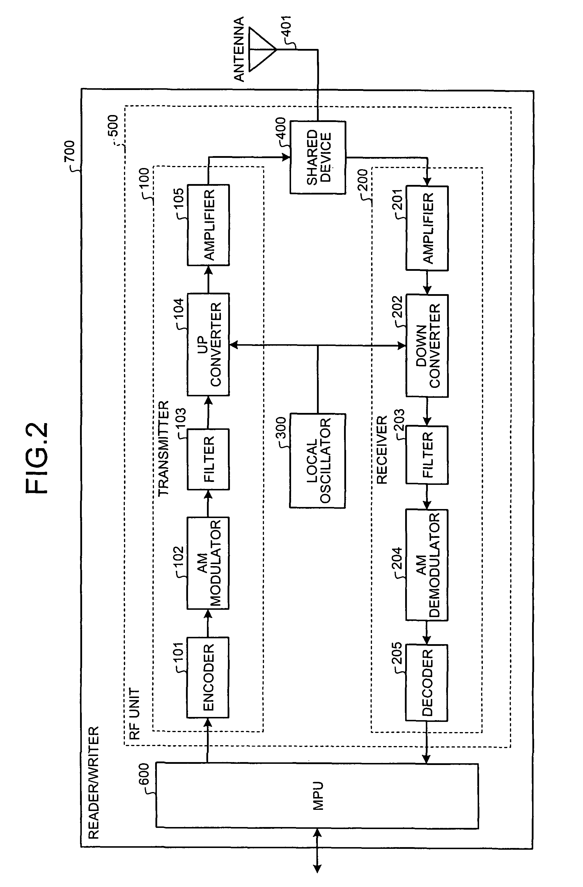
[0025]FIG. 2 is a functional block diagram of the structur...


PUM


Abstract

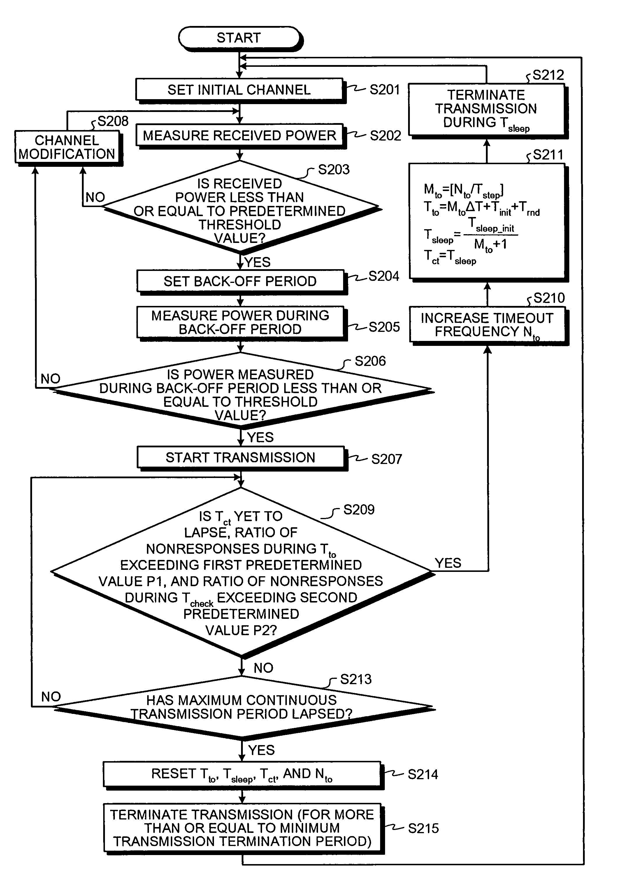
A nonresponse-ratio determining unit determines, after starting a signal transmission to an electronic tag, whether a ratio of number of nonresponses from the electronic tag exceeded a predetermined value in a first predetermined period. A signal-transmission terminating unit terminates, when it is determined that the ratio of the number of nonresponses exceeded the predetermined value, the signal transmission for a second predetermined period. A radio-frequency-identification interrogator performs, after a lapse of the second predetermined period, a communication-channel selecting process for restarting the signal transmission to the electronic tag.

Description

BACKGROUND OF THE INVENTION[0001]1. Field of the Invention[0002]The present invention relates to a technology for performing a carrier sensing for selecting, upon stipulation of a maximum continuous transmission period for continuously transmitting signals to an electronic tag and a minimum transmission termination period for terminating the signal transmission after lapse of the maximum continuous transmission period, an appropriate frequency to be used in the signal transmission during the minimum transmission termination period before transmitting a signal to the electronic tag.[0003]2. Description of the Related Art[0004]Recently, a radio frequency identification (RFID) is one of the emphasized technologies in ubiquitous society. A system that uses the RFID includes interrogators such as reader / writers, readers etc., and responding devices such as electronic tags, wireless integrated-circuit (IC) tags, wireless tags, and RFID tags. For example, in a widely known RFID system, the...

Claims


Application Information

Patent Timeline
Patent Type & Authority Patents(United States)
IPC IPC(8): G08B13/14
CPCG06K7/0008G06K7/10128G06K7/10356
Inventor TANAKA, YOSHINORI
Owner FUJITSU LTD
Learn More