Supercharge Your Innovation With Domain-Expert AI Agents!

Systems and methods for inducing swirl in particles

a technology of system and particle, applied in the field of particle separation, can solve the problems of affecting the operation of the device with which the gaseous stream is associated, affecting and reducing the efficiency of centrifugation

Inactive Publication Date: 2011-06-21
GENERAL ELECTRIC CO
View PDF22 Cites 7 Cited by
  • Summary
  • Abstract
  • Description
  • Claims
  • Application Information

AI Technical Summary

Benefits of technology

This method effectively separates and removes particles of varying sizes with reduced mechanical wear and pressure drops, improving operational efficiency and flexibility in particle handling within gaseous streams.

Problems solved by technology

Filtration requires that the filter be cleared or replaced, thus disturbing the operation of the device with which the gaseous stream is associated.
However, centrifugation is limited by particle size and mass constraints because the smaller the particle, the less effective the centrifugation becomes.
Increased velocities result in greater pressure drops and more mechanical wear on the hardware, reducing the overall operating efficiency and longevity of the device.
However, agglomeration techniques decrease the effectiveness and efficiency of the additional particle removal method.
For example, the above-discussed methods often result in a pressure drop in the gaseous stream, decreasing the efficiency of gas flow.
Additionally, some of the above-discussed methods are limited by particle size or type, and do not provide a flexible, adjustable method of removing particles from a gaseous stream.
Furthermore, the mechanical vortexing or centrifugation techniques require increasing the gas velocity introduced to increase the rotational velocity, which increases the resultant pressure drop and increases wear in the hardware.

Method used


Image

  • Systems and methods for inducing swirl in particles
  • Systems and methods for inducing swirl in particles
  • Systems and methods for inducing swirl in particles

Examples


Embodiment Construction

[0020]Example embodiments of the invention now will be described more fully hereinafter with reference to the accompanying drawings, in which some, but not all embodiments are shown. Indeed, the invention may be embodied in many different forms and should not be construed as limited to the embodiments set forth herein; rather, these embodiments are provided so that this disclosure will satisfy applicable legal requirements. Like numbers refer to like elements throughout.

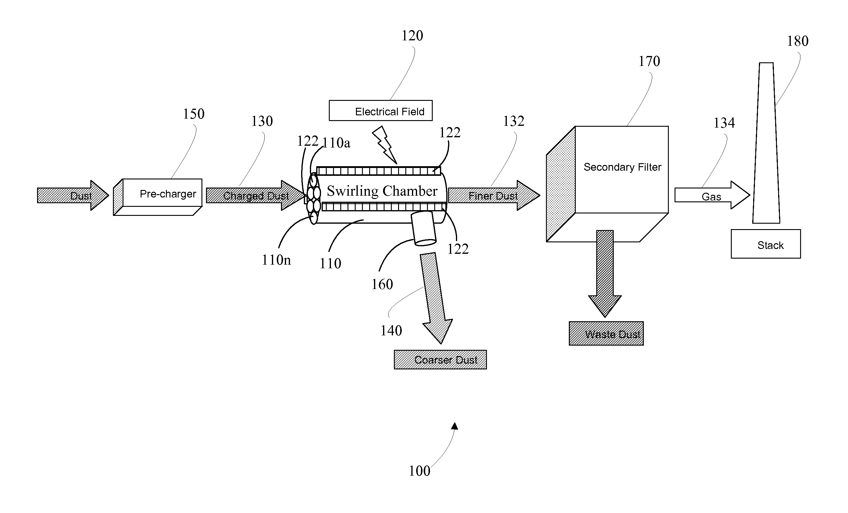
[0021]Systems and methods for inducing swirl in particles are provided for and described. Embodiments of these systems and methods can allow for inducing swirl in electrically charged particles, also referred to herein as ions, to facilitate particle separation, particle removal, agglomeration, and / or sorbent mixing in gas streams. In an example embodiment, at least one swirling chamber is positioned in a gas stream containing electrically charged particles. The swirling chamber may have an electrical field in the ch...


PUM


Abstract

Embodiments of systems and methods for inducing swirl in particles are provided. In one embodiment, a system for inducing swirl in particles may include a supply including a plurality of electrically charged particles, and at least one swirling chamber for creating at least one electrical field therein, which may include an entry path in communication with the supply and an exit path. According to this example embodiment, the plurality of electrically charged particles may flow through the swirling chamber or chambers, causing at least one of the plurality of electrically charged particles to rotate about a radial axis of the swirling chamber as a result of the electrical field.

Description

TECHNICAL FIELD[0001]The invention relates generally to particle separation and, more particularly, to systems and methods for inducing swirl in particles.BACKGROUND OF THE INVENTION[0002]Contaminants may exist in gaseous streams. In many industrial or commercial applications the contaminants must be at least partially separated or removed. Contaminants may be in the form of combustion bi-product, or may be dust, liquid, organic matter, or other particulates from various sources.[0003]Various techniques exist to attempt particle removal from gaseous streams. For example, filtration, washing, centrifugation or vortexing, agglomeration, and electrostatic precipitation are used for particle removal. Filtration, for example, passes the gaseous stream through a mechanical filter that may selectively trap particles of a given size. Filtration requires that the filter be cleared or replaced, thus disturbing the operation of the device with which the gaseous stream is associated. Washing in...

Claims


Application Information

Patent Timeline
Patent Type & Authority Patents(United States)
IPC IPC(8): B03C3/013B03C3/15
CPCB03C3/368
Inventor YOUNSI, ABDELKRIMTAYLOR, ROBERT WARREN
Owner GENERAL ELECTRIC CO
Features
  • R&D
  • Intellectual Property
  • Life Sciences
  • Materials
  • Tech Scout
  • Unparalleled Data Quality
  • Higher Quality Content
  • 60% Fewer Hallucinations
Learn More