Check patentability & draft patents in minutes with Patsnap Eureka AI!

Liquid fuel cell with a planer electrolyte layer

a fuel cell and electrolyte layer technology, applied in the field of liquid fuel cells, can solve the problems of large self-discharge, large total cell thickness, and inability to guarantee sufficient hours of continuous use of lithium ion secondary batteries

Inactive Publication Date: 2011-08-16
HITACHI MAXELL ENERGY LTD
View PDF29 Cites 0 Cited by
  • Summary
  • Abstract
  • Description
  • Claims
  • Application Information

AI Technical Summary

Benefits of technology

[0027]Additionally, in the liquid fuel cell of one embodiment of the present invention, it is preferable that the catalyst layer of the negative electrode contains a binder having no ionic conductivity and no fluorine. This increases the wettability between the negative electrode and the liquid fuel, thus improving the electrode characteristics. Therefore, it becomes possible to improve the discharge characteristics of the unit fuel cell. Further, since the binder has no ionic conductivity, the binder does not swell or melt easily owing to the liquid fuel. Thus, the cell stability increases, making it possible to improve the reliability of the fuel cell.

Problems solved by technology

However, depending on the kinds of cordless equipment to be used, this lithium ion secondary battery has not yet been able to guarantee sufficient hours of continuous use.
However, this air cell has a problem that an alkali solution used as an electrolyte solution reacts with carbon dioxide in the air and degrades, leading to a large self-discharge.
However, since a conventional fuel cell has been constituted by layering a plurality of unit fuel cells, the total cell thickness is large.
However, this may cause problems that an output drops and that gases such as carbon dioxide generated in a discharge reaction build up in a fuel chamber and thus, with a consumption of the fuel, the fuel loses contact with the negative electrode.
However, depending on the composition of the fuel, more specifically, in the case of using an alcohol aqueous solution with high concentration, there is a problem that the fuel passes through the porous film and leaks out.
This easily causes a problem that miniaturization to a certain extent or more becomes difficult.
On the other hand, in the negative electrode where the reaction of methanol serving as a liquid fuel is to occur, the liquid fuel cannot be oxidized easily owing to poor wettability of the electrode if the electrode has water repellency.
Therefore, the negative electrode itself has not necessarily had an optimal structure.

Method used


Image

  • Liquid fuel cell with a planer electrolyte layer
  • Liquid fuel cell with a planer electrolyte layer
  • Liquid fuel cell with a planer electrolyte layer

Examples


first embodiment

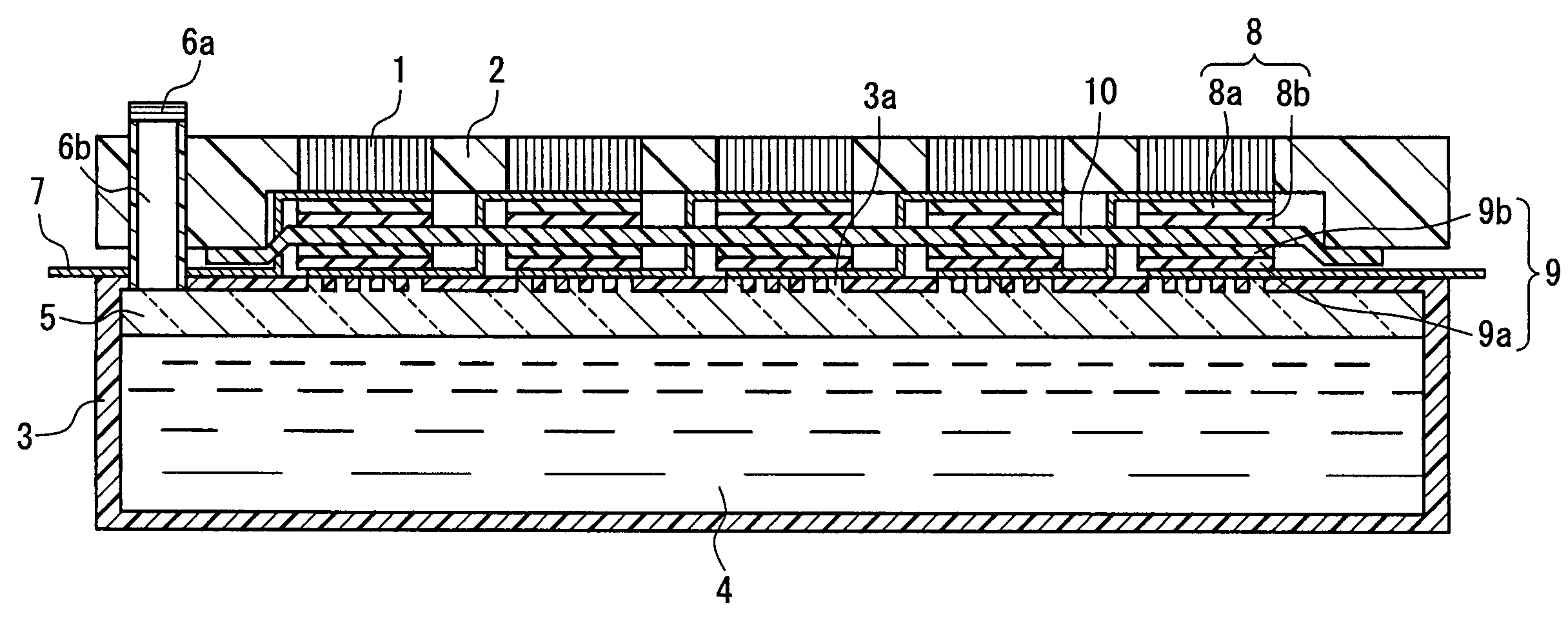
[0029]FIG. 1 is a sectional view showing a liquid fuel cell of the first embodiment of the present invention. A positive electrode 8 is a laminate including a diffusion layer 8a formed of a porous carbon material, for example, and a catalyst layer 8b containing catalyst-carrying carbon powder, a proton conducting substance and a fluorocarbon resin binder. The positive electrode 8 has a function of reducing oxygen, and for the catalyst therein, platinum fine particles or fine particles of an alloy of platinum with iron, nickel, cobalt, tin, ruthenium or gold can be used, for example. The proton conducting substance can be, for example, a resin having a sulfonic acid group such as a polyperfluorosulfonic acid resin, a sulfonated polyethersulfonic acid resin or a sulfonated polyimide resin but is not limited to the above. It is preferable that the content of this proton conducting substance is 2 to 200 parts by mass with respect to 100 parts by mass catalyst carrying carbon powder. Wit...

second embodiment

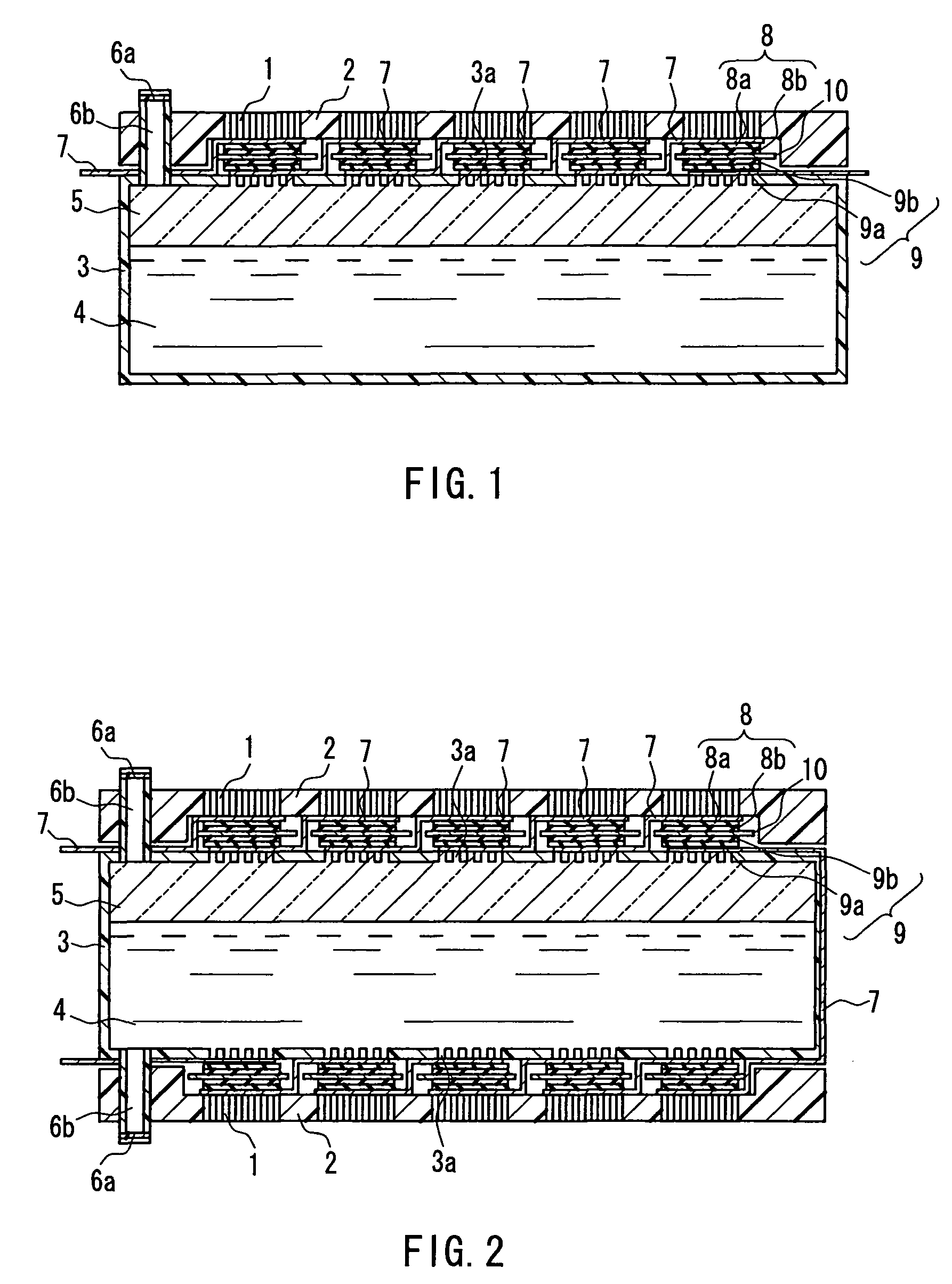
[0057]FIG. 2 is a sectional view showing a liquid fuel cell of the second embodiment of the present invention. The present embodiment is directed to a structure similar to that in the first embodiment except that portions above and below the fuel tank 3 are formed to be substantially symmetrical.

third embodiment

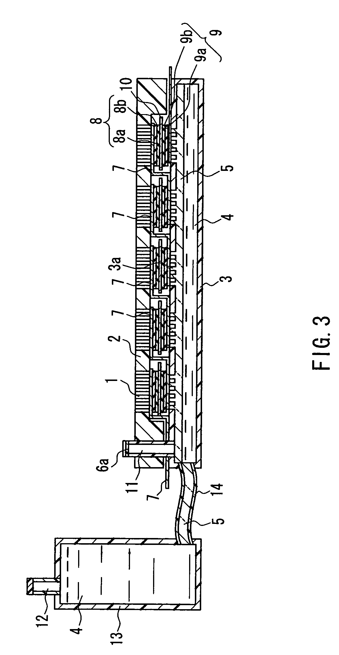
[0058]FIG. 3 is a sectional view showing a liquid fuel cell of the third embodiment of the present invention. In the present embodiment, the fuel tank 3 and an outside fuel tank 13 are connected by a fuel supply passage 14 having the fuel suction material 5 therein. The fuel tank 13 is filled with the liquid fuel 4 similarly to the fuel tank 3 and has a function of supplying the liquid fuel 4 continuously through the fuel supply passage 14. The fuel tank 13 can be formed of, for example, a material similar to that for the fuel tank 3. The fuel supply passage 14 can be formed of, for example, a material similar to that for the fuel tank 3 or a flexible rubber such as a natural rubber. The fuel tank 13 has a fuel filling port 12 and a function of additionally filling the liquid fuel. Numeral 11 denotes a gas-liquid separation hole. Other structures of the present embodiment are substantially the same as that of the first embodiment.


PUM

PropertyMeasurementUnit
particle diameteraaaaaaaaaa
pressureaaaaaaaaaa
pressureaaaaaaaaaa

Abstract

A liquid fuel cell comprising a plurality of unit fuel cells each having a positive electrode (8) for reducing oxygen, a negative electrode (9) for oxidizing liquid fuel, and an electrolyte layer (10) interposed between the positive electrode (8) and the negative electrode (9), and a section (3) for storing liquid fuel (4), wherein power can be generated stably while reducing the size by arranging the plurality of unit fuel cells on the substantially same plane. Each electrolyte layer of the unit fuel cell preferably constitutes a continuous integrated electrolyte layer.

Description

TECHNICAL FIELD[0001]The present invention relates to a liquid fuel cell.BACKGROUND ART[0002]In recent years, along with the widespread use of cordless equipment such as personal computers and cellular phones, a smaller and higher-capacity secondary battery serving as a power source thereof has been much in demand. At present, as a secondary battery that has a high energy density and can be reduced in size and weight, a lithium ion secondary battery is being commercialized. The demand therefor as a portable power source is increasing. However, depending on the kinds of cordless equipment to be used, this lithium ion secondary battery has not yet been able to guarantee sufficient hours of continuous use.[0003]Under such circumstances, as an example of a battery capable of satisfying the above-described demand, an air cell and a fuel cell can be considered. An air cell is considered to be suitable for increasing energy density because it utilizes oxygen in the air as a positive active...

Claims


Application Information

Patent Timeline
Patent Type & Authority Patents(United States)
IPC IPC(8): H01M8/10H01M8/04H01M8/24
CPCH01M8/04186H01M8/2455H01M8/1009H01M8/1004Y02E60/521Y02E60/50H01M8/04H01M8/10
Inventor KASHINO, HIROSHIARISHIMA, YASUOSHIBATA, SHINSUKESEKI, GUNSAIBARA, SHOJINAGAI, RYO
Owner HITACHI MAXELL ENERGY LTD
Features
  • R&D
  • Intellectual Property
  • Life Sciences
  • Materials
  • Tech Scout
  • Unparalleled Data Quality
  • Higher Quality Content
  • 60% Fewer Hallucinations
Learn More