Check patentability & draft patents in minutes with Patsnap Eureka AI!

Liquid crystal display device

a liquid crystal display and display device technology, applied in non-linear optics, instruments, optics, etc., can solve the problems of undesired light leakage, excessive blue image, color washout, etc., and achieve the effect of reducing undesired light leakage and higher contrast ratio

Active Publication Date: 2011-09-06
AU OPTRONICS CORP
View PDF5 Cites 0 Cited by
  • Summary
  • Abstract
  • Description
  • Claims
  • Application Information

AI Technical Summary

Benefits of technology

This configuration effectively reduces light leakage in the dark state, increases the contrast ratio, and prevents color washout by compensating for phase differences and providing tailored gamma signals for each color pixel, resulting in improved image quality.

Problems solved by technology

As a result, when images are displayed in the dark state, viewers may see undesired light leakage from a wide angle.
Consequently, the color washout problem occurs.
Therefore, when a black image is displayed, an excessively blue image often appears.

Method used


Image

  • Liquid crystal display device
  • Liquid crystal display device
  • Liquid crystal display device

Examples


Embodiment Construction

[0023]To provide a better understanding of the presented invention, preferred embodiments will be detailed as follows. The preferred embodiments of the present invention are illustrated in the accompanying drawings with numbered elements to elaborate the contents and effects to be achieved.

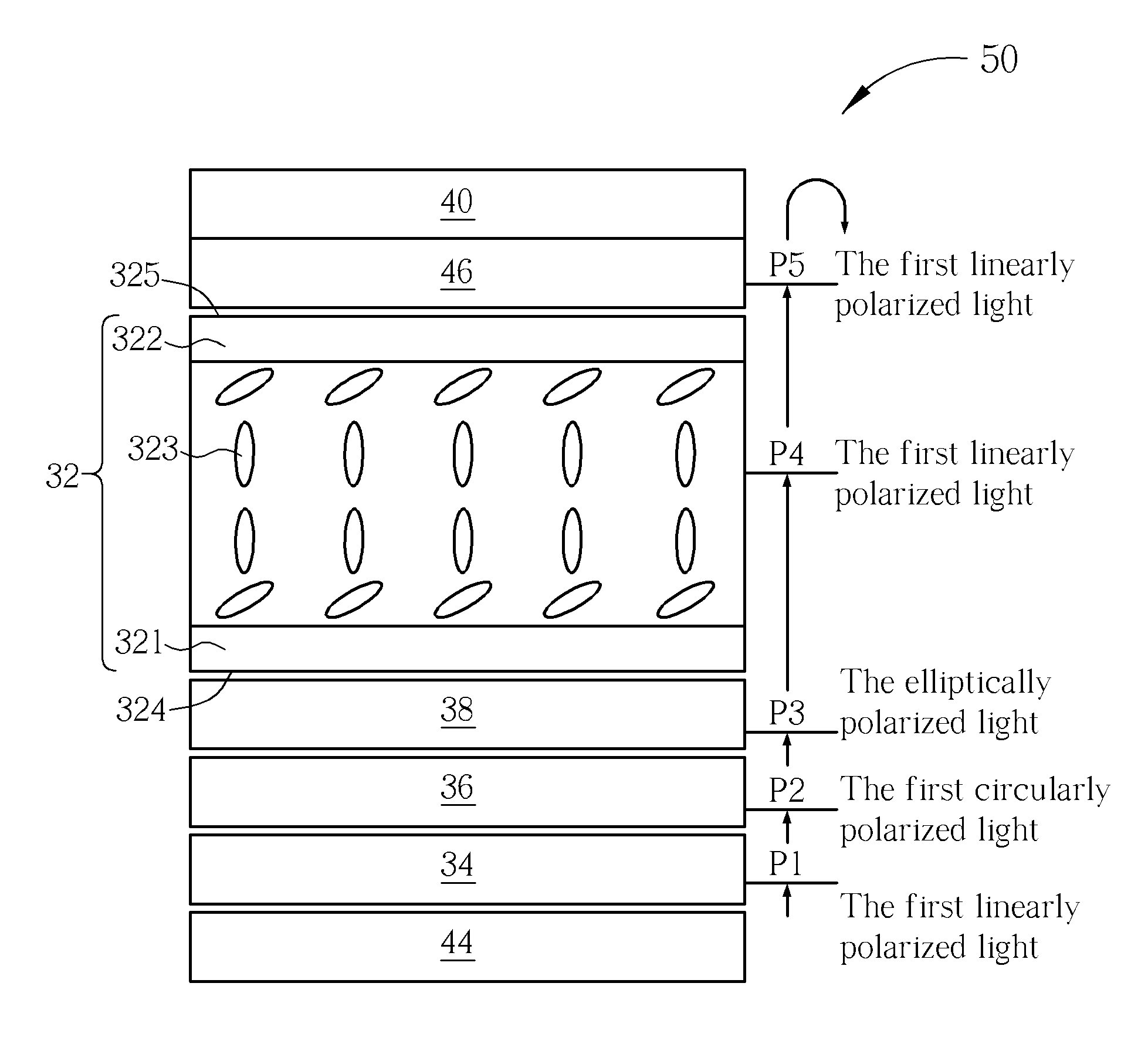
[0024]With reference to FIG. 3 and FIG. 4, FIG. 3 and FIG. 4 are schematic diagrams illustrating a preferred embodiment of an LCD device of the present invention. FIG. 3 is a cross-sectional schematic diagram illustrating an LCD device of the present embodiment. FIG. 4 is a schematic diagram illustrating the relationship of the slow axis or the transmissive axis direction of each of the films of an LCD device of the present embodiment. As illustrated in FIG. 3, the LCD device 30 of the present embodiment includes an LCD panel 32, a first polarizer 34, a first quarter-wave retardation film 36, a hybrid aligned nematic film 38, a second polarizer 40, a multiple-gamma IC 42 and a backlight module 44....


PUM

PropertyMeasurementUnit
included angleaaaaaaaaaa

Abstract

A liquid crystal display device uses a first quarter-wave retardation film and a hybrid aligned nematic film to reduce light leakage in dark state for reaching high contrast ratio, and uses multiple-gamma IC to provide different gamma-curve signals for pixels of different colors to solve color shift problem. In addition, the liquid crystal display device may use a second quarter-wave retardation film to reduce light leakage when viewed in a wide angle so as to further provide higher contrast ratio.

Description

BACKGROUND OF THE INVENTION[0001]1. Field of the Invention[0002]The present invention relates to a liquid crystal display (LCD) device, and more particularly, to an LCD device having advantages of high contrast ratio, wide view angle and low color washout.[0003]2. Description of the Prior Art[0004]Since electrically controlled birefringence (ECB) LCD devices have advantages, such as higher aperture ratio and simple manufacturing process, the ECB LCD devices have become one of the widely prevailing LCDs nowadays. With reference to FIG. 1 and FIG. 2, FIG. 1 and FIG. 2 are schematic diagrams of a conventional ECB LCD panel. FIG. 1 is a schematic diagram illustrating a conventional ECB LCD panel in / under the bright state, and FIG. 2 is a schematic diagram illustrating a conventional ECB LCD panel in / under the dark state. The ECB LCD panel 10 is a normally white LCD panel. The ECB LCD panel includes two substrates 12, 14, and liquid crystal molecules 16 sealed therebetween. The liquid cr...

Claims


Application Information

Patent Timeline
Patent Type & Authority Patents(United States)
IPC IPC(8): G02F1/1335
CPCG02F1/133632G02F1/1393G02F2001/133633G02F2001/133638G02F2413/02G02F2413/07G02F1/133633G02F1/133638
Inventor LO, CHENGLIN, YUNG-LUNCHENG, CHING-SHENGHU, CHIH-JEN
Owner AU OPTRONICS CORP
Features
  • R&D
  • Intellectual Property
  • Life Sciences
  • Materials
  • Tech Scout
  • Unparalleled Data Quality
  • Higher Quality Content
  • 60% Fewer Hallucinations
Learn More