Check patentability & draft patents in minutes with Patsnap Eureka AI!

IR camera

a technology of image stabilization and ir camera, which is applied in the field of image stabilization of ir camera, can solve the problems of inability to use ir camera, and achieve the effect of small size and convenient operation

Inactive Publication Date: 2011-09-13
FLIR SYST AB
View PDF3 Cites 0 Cited by
  • Summary
  • Abstract
  • Description
  • Claims
  • Application Information

AI Technical Summary

Benefits of technology

The solution provides effective image stabilization for IR cameras by compensating for camera movements around both pitch and yaw axes, ensuring a stable image while maintaining a compact and easy-to-operate design.

Problems solved by technology

This is not feasible for IR cameras since the sensor array in such cameras typically requires cooling.

Method used


Image

  • IR camera
  • IR camera
  • IR camera

Examples


Embodiment Construction

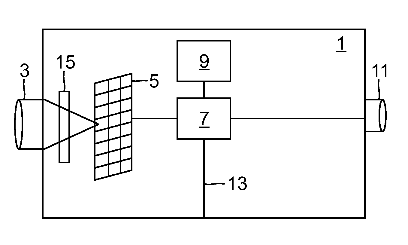
[0022]FIG. 1 is a schematic overview of an IR camera 1 according to an overall embodiment of the invention. As is common in the art, the IR camera 1 has an optical system 3 for focusing incoming infrared radiation onto a sensor array 5. The signals from the sensor array are processed in a processing device 7 to produce an IR image and possibly other data that may be displayed to a user of the camera, in ways that are common in the art. The camera may also comprise a memory unit 9 for storing the processed data, a display unit 11 for displaying the image and / or other data to the user, and / or one or more external connections 13 for communication with external devices (not shown), such as a computer.

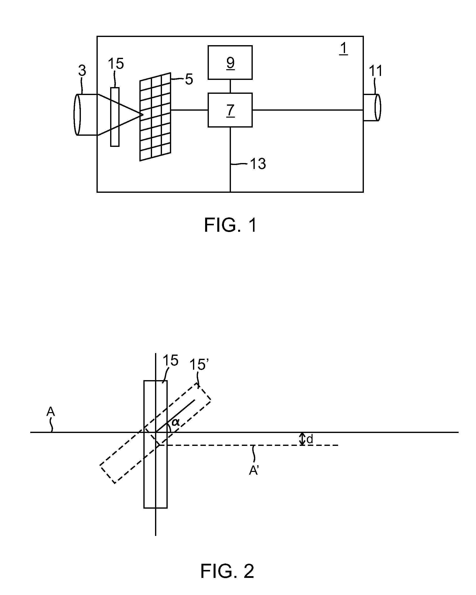
[0023]The optical system 3 typically comprises one or more lenses and control devices for controlling the position of these lenses for focusing the incoming radiation onto the sensor array 5. To compensate for the movements of the camera, according to the invention, a plane disc 15 of a mat...


PUM


Abstract

An IR camera comprising an optical system further comprises an additional optical element arranged in the form of a disk that is transparent to the infrared radiation in the beam path and at least a first motor arranged to tilt the additional optical element around a first axis substantially perpendicular to the beam path, and a control device for controlling said at least first motor in dependence of a first registered movement of the camera.

Description

TECHNICAL FIELD [0001]The present invention relates to image stabilization in an IR camera.BACKGROUND AND RELATED ART[0002]In practice, a hand-held camera will always shake a little. The movements will primarily be around a horizontal axis (yaw) and a vertical axis (azimuth or pitch). The magnitude of the movements will depend on the type of camera and other conditions, but will typically be in the order of ±0.15°.[0003]The movements will normally have a frequency of up to 15 Hz. Movements in this frequency range can be compensated for by means of an image stabilization system. It is known to use one or more prisms or lenses to compensate for the movements and thereby stabilize the image.[0004]U.S. Pat. No. 5,774,266 discloses an image stabilization system using a lens for deflecting the incoming radiation. The relative inclination between the optical axis of the photographic optical system and the optical axis 101a of the correcting lens 101 of the correcting optical mechanism whic...

Claims


Application Information

Patent Timeline
Patent Type & Authority Patents(United States)
IPC IPC(8): G02B13/14
CPCG02B27/646H04N5/23248H04N5/23254H04N5/23258H04N5/23287H04N5/33G02B13/14H04N23/6811H04N23/68H04N23/6812H04N23/687H04N23/20
Inventor STROMBERG, CHRISTOFFERGUSTAFSSON, OVE
Owner FLIR SYST AB
Features
  • R&D
  • Intellectual Property
  • Life Sciences
  • Materials
  • Tech Scout
  • Unparalleled Data Quality
  • Higher Quality Content
  • 60% Fewer Hallucinations
Learn More