Supercharge Your Innovation With Domain-Expert AI Agents!

Hermetic compressor

a compressor and hermetic technology, applied in the direction of piston pumps, pump parameters, instruments, etc., can solve the problems of poor operation, short service life, failure of lubrication, etc., and achieve the effect of simple construction and reliability of refrigerators

Inactive Publication Date: 2011-09-20
PANASONIC CORP
View PDF10 Cites 7 Cited by
  • Summary
  • Abstract
  • Description
  • Claims
  • Application Information

AI Technical Summary

Benefits of technology

The solution enhances compressor reliability by enabling precise oil surface detection, preventing lubrication issues and maintaining airtight performance, thus stabilizing refrigeration device performance.

Problems solved by technology

However, the amount of the oil varies depending on the operation, and it sometimes becomes short and fails in lubrication.
To the contrary, if the oil is pooled excessively, a large amount of the refrigerating machine oil is discharged together with compressed refrigerant gas from compressor 51, thereby inviting lower performance of a heat exchanger as well as of the refrigerator.
The foregoing structure needs two thermistors and connections between the termistors and the hermetic terminal, so that the structure becomes complex and causes poor operation, and invites lower reliability because of a possible disconnection.
Some of conventional compressors employ a single thermistor, which however simply measures a temperature, so that an accurate detection of the oil surface cannot be expected.
However, since the side-wall is shaped like a cylinder, the mounting of the sensor onto the side-wall will invite a defect in airtight performance due to distortion, or causes a failure in airtight performance due to a collision in assembling the compressor.
This delay further lowers the oil surface.
This phenomenon sometimes causes serious damage to the compressor.
On top of that, employment of sensors for detecting simply a temperature of the refrigerant gas and that of the refrigerating machine oil sometimes shows temperatures similar to each other depending on an operating condition, and an operation during a transition period particularly causes the sensors to malfunction.

Method used


Image

  • Hermetic compressor
  • Hermetic compressor
  • Hermetic compressor

Examples


exemplary embodiment 1

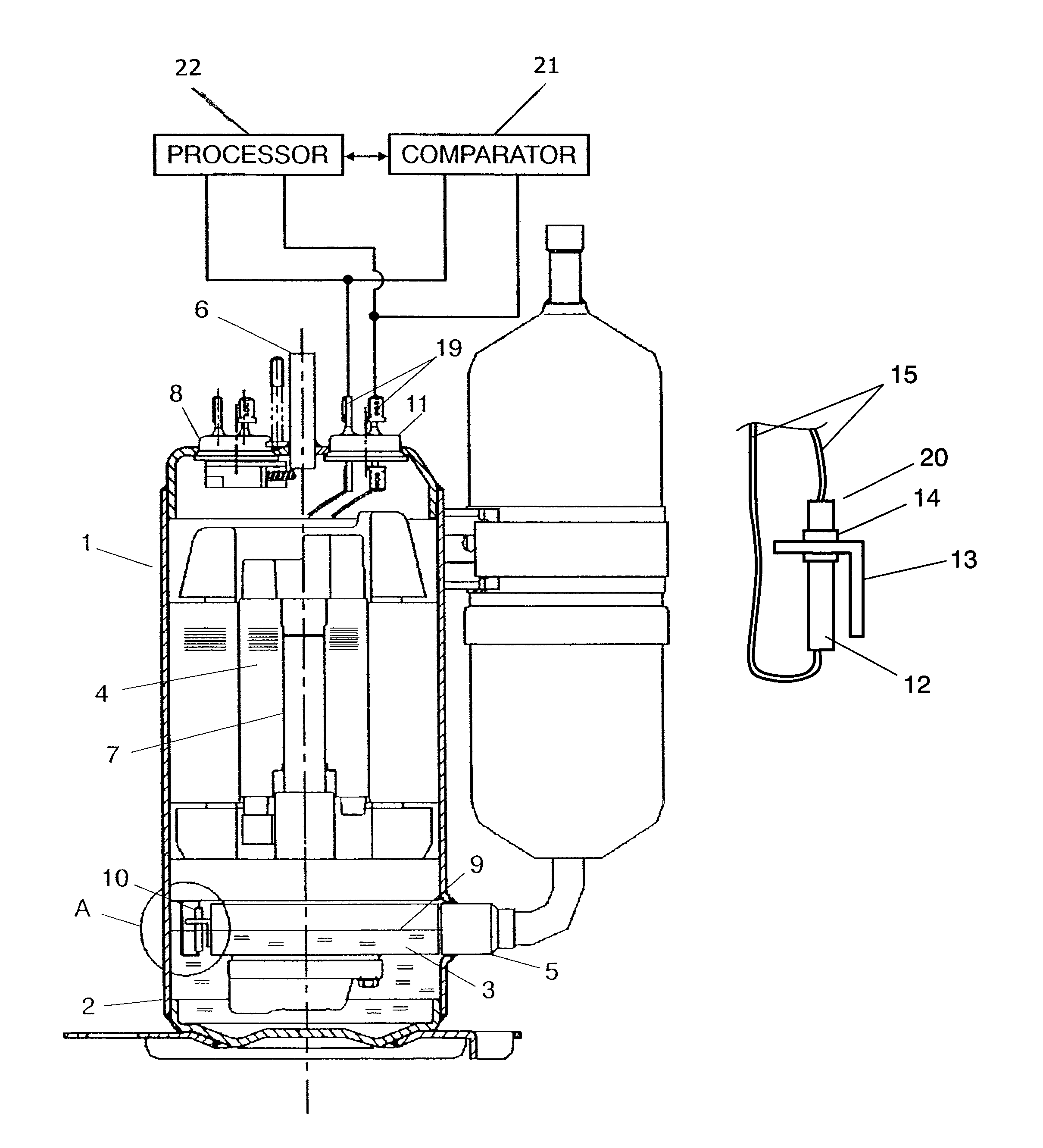
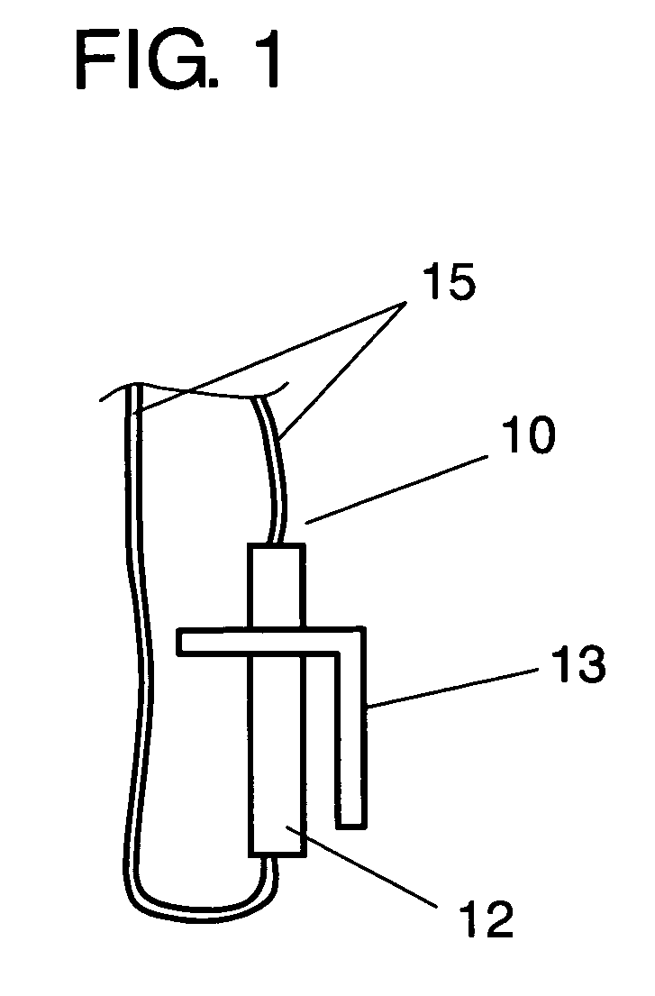
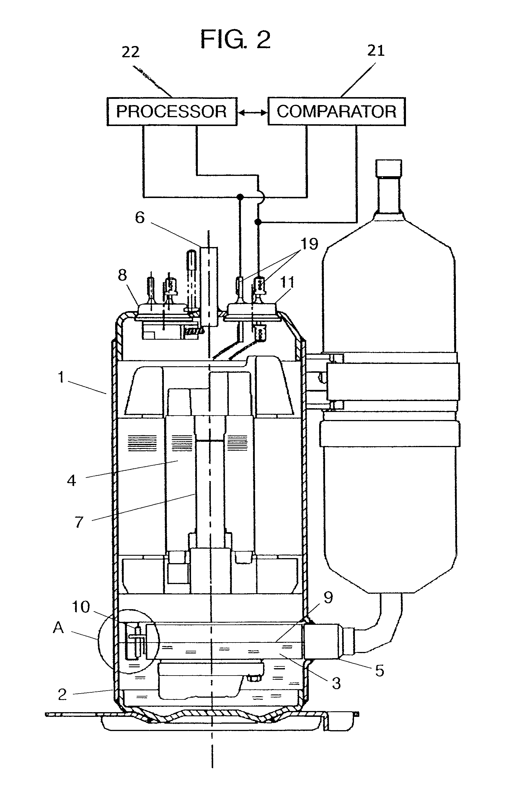
[0028]FIG. 1 shows oil surface sensor 10 placed in a compressor in accordance with the first exemplary embodiment of the present invention. FIG. 2 shows a schematic diagram illustrating the compressor in accordance with the first exemplary embodiment, and FIG. 3 shows an enlarged view of section A shown in FIG. 2.

[0029]In FIG. 2, compressor 1 is formed of compressing mechanism 3 and motor 4 both accommodated in cylindrical housing 2. In other words, compressor 1 shapes like a high pressure dome. Housing 2 is equipped with discharge tube 6 at its upper end for discharging compressed refrigerant gas.

[0030]Compressing mechanism 3 is a rolling piston model and rigidly mounted to housing 2, and connected with sucking tube 5 for feeding refrigerant gas into housing 2. Compressing mechanism 3 is coupled to motor 4 with driving shaft 7, so that it is driven by motor 4.

[0031]Motor 4 is disposed above compressing mechanism 3 and connected to hermetic terminal 8 welded at the upper end of hous...

exemplary embodiment 2

[0045]The compressor in accordance with the second exemplary embodiment of the present invention is constructed similar to that in the first embodiment. Different points from the first one are detailed hereinafter.

[0046]As shown in FIG. 4, oil surface sensor 20 in accordance with the second embodiment senses a temperature with thermistor 12, and also senses a rate of change in temperature onward for detecting a position of oil surface 9. Heat insulator 14 is employed between thermistor 12 and holder 13 that anchors thermistor 12. Holder 13 is fixed to compressing mechanism 3 with bolts, and is preferable to be a metallic holder for stronger fixation. In such a case, a temperature in the compressing mechanism travels through the holder to thermistor 12 and tends to invite an error in sensing the temperature. Thus heat insulator 14 is placed between holder 13 and thermistor 12 to prevent the temperature from traveling to thermistor 12. Heat insulator 14 is made of material having a lo...


PUM


Abstract

A hermetic compressor includes a housing accommodating a motor and a compressing mechanism driven by the motor, refrigerating machine oil, which is pooled in the housing, for lubricating the compressing mechanism, refrigerant gas sealed into the housing and to be refrigerant forming a refrigerating cycle, and an oil surface sensor including a thermistor having a given length. A part of the oil surface sensor is impregnated into the refrigerating machine oil, and the sensor senses a temperature immediately after energizing the thermistor and a rate of change in temperature onward, so that a position of an oil surface is detected.

Description

FIELD OF THE INVENTION[0001]The present invention relates to hermetic compressors to be mounted in air-conditioners or refrigerators and used for compressing refrigerant.BACKGROUND OF THE INVENTION[0002]A conventional hermetic compressor (hereinafter referred to simply as “compressor”), which is formed of a compressing mechanism and an electric motor both accommodated in a housing hermetically welded, is disclosed in Japanese Patent Unexamined Publication No. H06-159274. This compressor is free from refrigerant leakage or water invasion, so that it has been widely used in air-conditioners or refrigerators because of its high reliability.[0003]FIG. 5 shows a sectional view of a conventional compressor. In FIG. 5, compressing mechanism 53 and electric motor 54 are accommodated in cylindrical housing 52 to form a compressor of a high-pressure dome model. Housing 52 is equipped with discharging tube 56 at its upper end for discharging compressed refrigerant gas.[0004]Compressing mechani...

Claims


Application Information

Patent Timeline
Patent Type & Authority Patents(United States)
IPC IPC(8): F04B39/04G01F23/24
CPCF04B39/0207F04B39/023F04C23/008F04C28/28F04C29/02F04B2201/0402F04C2270/70
Inventor URATANI, AKIO
Owner PANASONIC CORP
Features
  • R&D
  • Intellectual Property
  • Life Sciences
  • Materials
  • Tech Scout
  • Unparalleled Data Quality
  • Higher Quality Content
  • 60% Fewer Hallucinations
Learn More