Supercharge Your Innovation With Domain-Expert AI Agents!

Multi-component transient fuel compensation

a transient fuel and multi-component technology, applied in the direction of combustion air/fuel air treatment, electric control, instruments, etc., can solve the problems of requiring a significant amount of computational resources to run in real time, complex strategy, multi-component, etc., and achieve the effect of effective transient fuel compensation and degrading engine emissions

Inactive Publication Date: 2011-10-25
FORD GLOBAL TECH LLC
View PDF6 Cites 8 Cited by
  • Summary
  • Abstract
  • Description
  • Claims
  • Application Information

AI Technical Summary

Benefits of technology

Accordingly, in one example, some of the above issues may be addressed by a method of adjusting an amount of fuel injection to an engine based on an ethanol content of fuel in a port puddle. Further, in some embodiments, the adjustment may be further based on the percent ethanol of the injected fuel. Further, in some embodiments, such an approach may include determining the amount of fuel evaporated from the puddle based on selected components of the fuel and their respective vapor pressures via a multi-component fuel model. The vapor pressures may be identified via text-book values and, hence, may be accessed via a look-up table, for example, as opposed to via calibration. By reducing the amount of calibratable tables referenced in determining a fuel injection compensation, an amount of a fuel injection may be more efficiently and rapidly determined, as described in more detail herein.

Problems solved by technology

One of the issues that affects the accuracy of AFR regulation is that a fraction of injected fuel sticks to the port walls, in so-called “puddles.” Fuel from the puddles evaporates at a rate that depends on many factors including wall temperature, manifold pressure, and fuel volatility.
Engine control strategies may include compensation for the fuel-puddling (also called wall-wetting) effect, but the complexity of the underlying physics makes the strategy complicated and the calibration process time consuming.
Part of the complexity is due to the varying volatility of fuels available at the pump (e.g., depending on the season and location) and the requirement that some vehicles run on flex fuels which can be a variable mixture of gasoline and ethanol (C2H5OH), with up to 85% percent of ethanol.
The multi-component, multi-puddle models are complex and typically require a significant amount of computational resources to run in real time.
They are also nonlinear, and hence, not conducive for transient fuel puddle compensation.
The calibrations are typically time intensive and may not effectively compensate for the port puddling effect because the physics of the process is not captured well by the simplified model.
In particular, these models are not capable of tracking the fraction of ethanol in the port puddle as opposed to the fraction of ethanol in the tank.
Consequently, an effective transient fuel compensation may not be achieved, thereby degrading engine emissions.

Method used


Image

  • Multi-component transient fuel compensation
  • Multi-component transient fuel compensation
  • Multi-component transient fuel compensation

Examples


Embodiment Construction

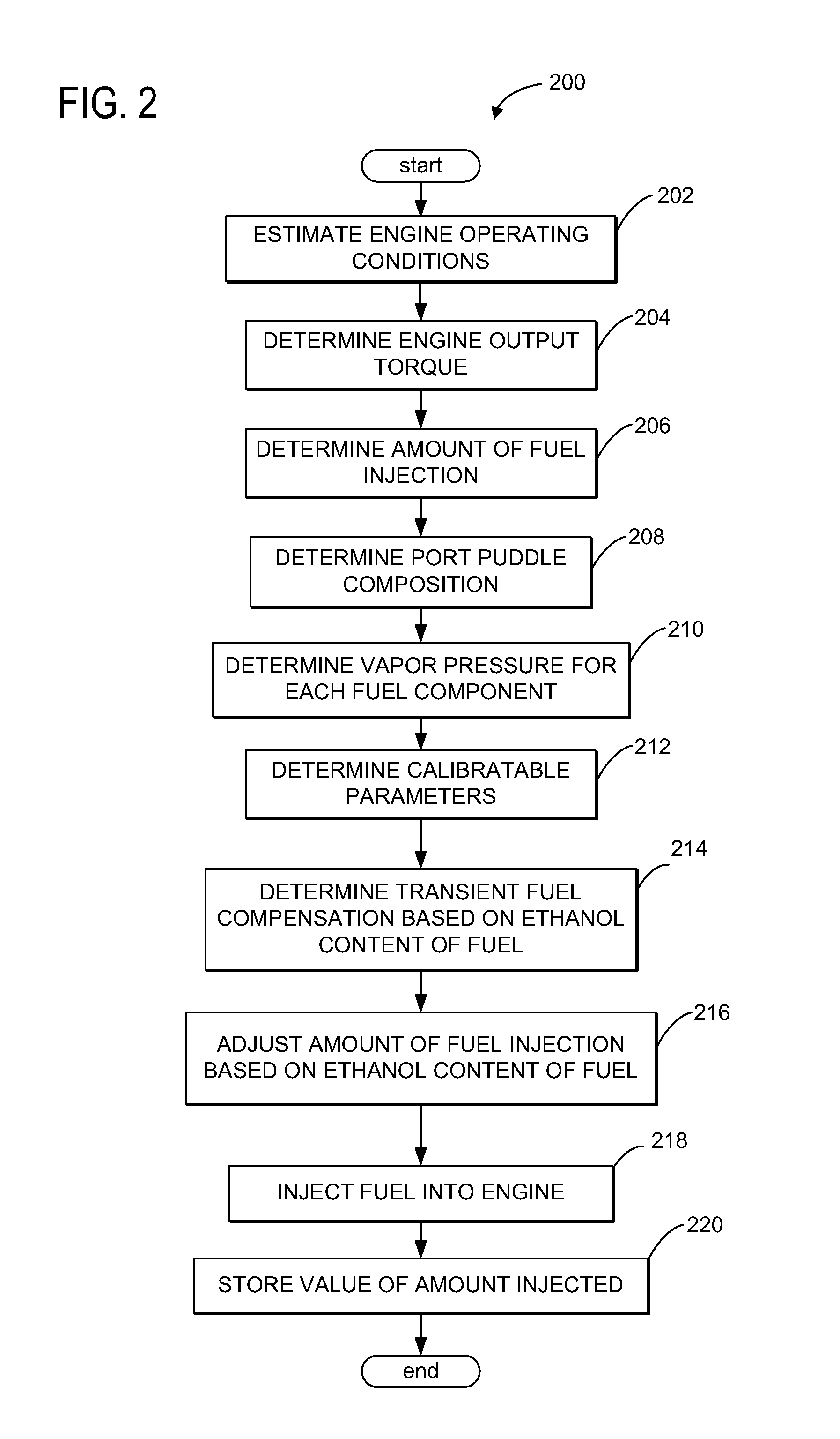
Embodiments of multi-component transient fuel compensation are disclosed herein. Such a transient fuel compensation may be utilized for adjusting an amount of a fuel injection to an engine based on an ethanol content of the fuel remaining in a port puddle from previous engine operations, as described in more detail hereafter.

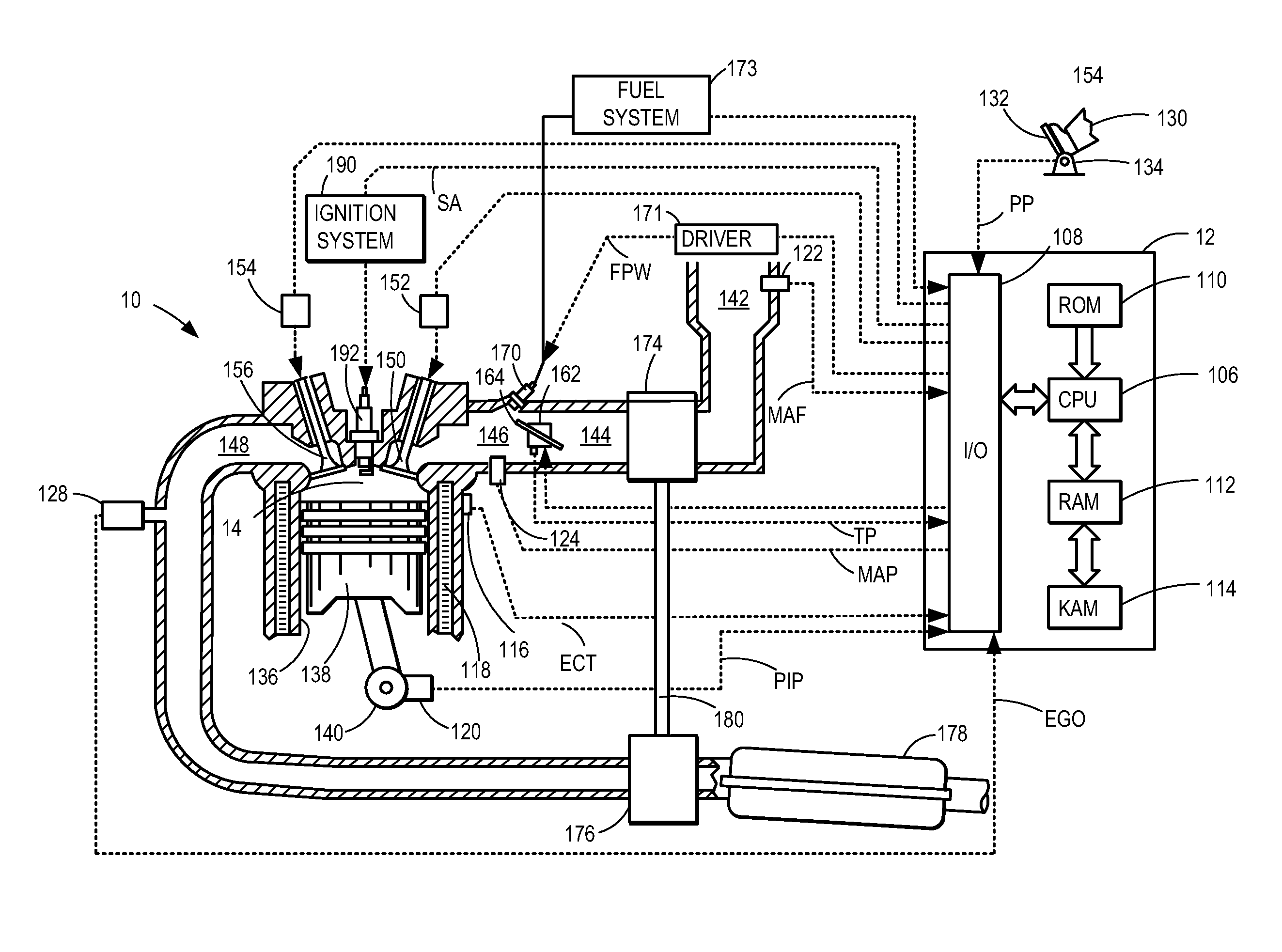
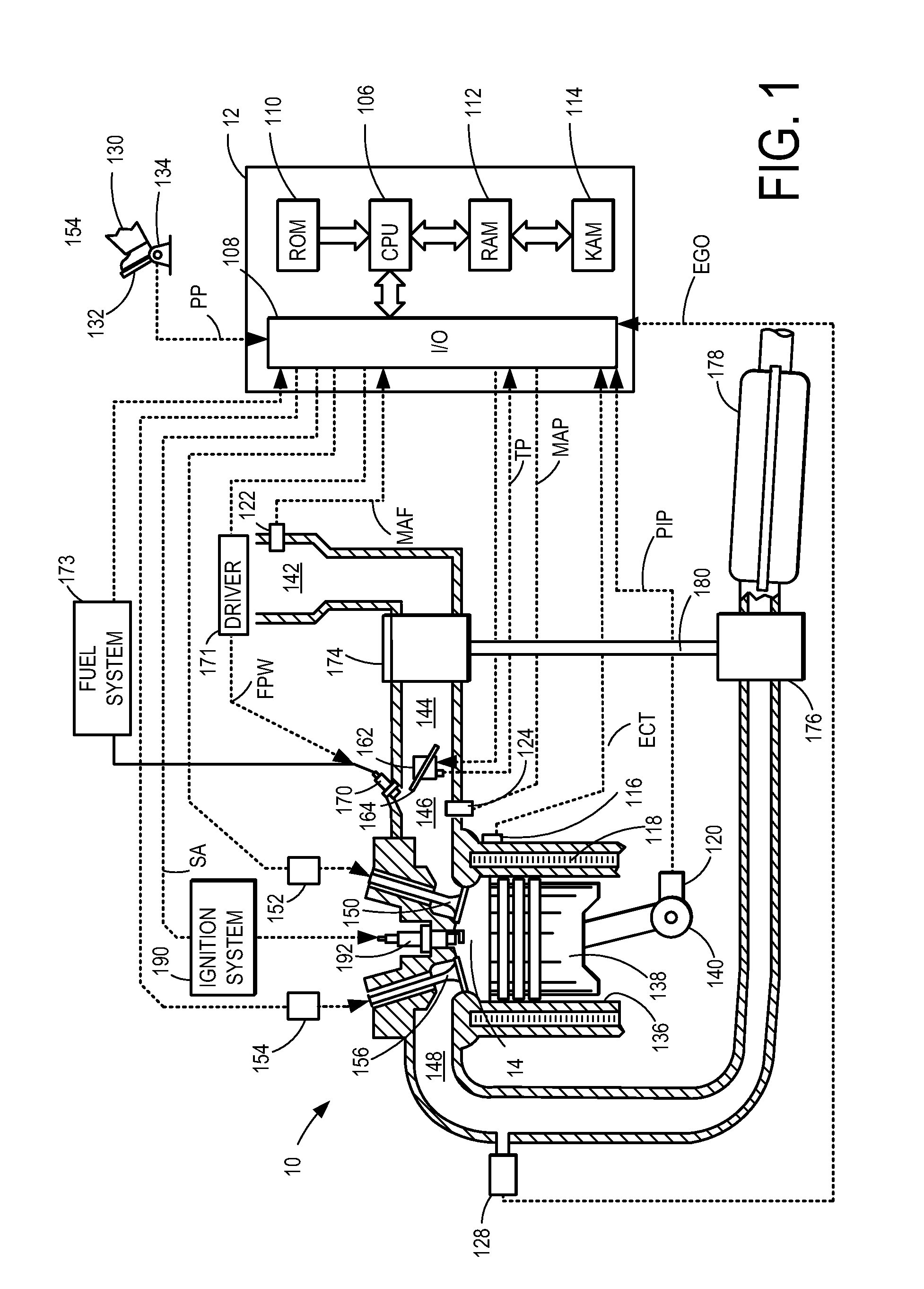
FIG. 1 depicts an example embodiment of a combustion chamber or cylinder of internal combustion engine 10. Engine 10 may be controlled at least partially by a control system including controller 12 and by input from a vehicle operator 130 via an input device 132. In this example, input device 132 includes an accelerator pedal and a pedal position sensor 134 for generating a proportional pedal position signal PP. Cylinder (also referred to as a combustion chamber) 14 of engine 10 may include combustion chamber walls 136 with piston 138 positioned therein. Piston 138 may be coupled to crankshaft 140 so that reciprocating motion of the piston is translated into rot...


PUM


Abstract

A method adjusts fuel injection to account for fuel puddling in the engine intake. The fuel is adjusted based on the ethanol content of the fuel in the puddle, and the make-up of the various fuel components in the puddle. In this way, it is possible to better account for the effects of these parameters on puddle evaporation.

Description

TECHNICAL FIELDThe present application relates to multi-component transient fuel compensation for flex fuel vehicles.BACKGROUND AND SUMMARYIn modern engines, the air-fuel ratio (AFR) in the cylinder may be controlled close to stoichiometry to maintain high emission conversion efficiency of the exhaust catalyst system. One of the issues that affects the accuracy of AFR regulation is that a fraction of injected fuel sticks to the port walls, in so-called “puddles.” Fuel from the puddles evaporates at a rate that depends on many factors including wall temperature, manifold pressure, and fuel volatility. Engine control strategies may include compensation for the fuel-puddling (also called wall-wetting) effect, but the complexity of the underlying physics makes the strategy complicated and the calibration process time consuming. Part of the complexity is due to the varying volatility of fuels available at the pump (e.g., depending on the season and location) and the requirement that some...

Claims


Application Information

Patent Timeline
Patent Type & Authority Patents(United States)
IPC IPC(8): F02M1/00
CPCF02D41/0025F02D41/047F02D2200/021F02D2041/1433F02D41/2451
Inventor JANKOVIC, MRDJAN J.COOPER, STEPHEN LEE
Owner FORD GLOBAL TECH LLC
Features
  • R&D
  • Intellectual Property
  • Life Sciences
  • Materials
  • Tech Scout
  • Unparalleled Data Quality
  • Higher Quality Content
  • 60% Fewer Hallucinations
Learn More