Aircraft landing gear compression rate monitor

a technology of compression rate monitor and landing gear, which is applied in the direction of navigation instruments, instruments, transportation and packaging, etc., can solve the problems of no devices certified by the faa and installed on aircraft, overweight landing event, and increased pressure within the shock absorber

Active Publication Date: 2011-10-25
NANCE C KIRK
View PDF36 Cites 74 Cited by
  • Summary
  • Abstract
  • Description
  • Claims
  • Application Information

AI Technical Summary

Benefits of technology

[0021]In accordance with another aspect of the present invention, the step of photographing moving and non-moving...

Problems solved by technology

Aircraft have limitations regarding the maximum allowable force the aircraft landing gear and other supporting structures of the aircraft can safely absorb when the aircraft lands.
This causes an overweight landing event.
Currently there are no devices certified by the FAA and installed on aircraft to measure and monitor individual landing gear compression rates nor the aircraft descent velocity at initial contact with the ground.
As the landing gear comes into initial contact with the ground, the strut begins to compress, thereby increasing the pressure within the shock absorber.
Though the approach may appear valid, it is subject to error by its inability to verify, at any given landing event, the exact proportion of gas volume in relation to hydraulic oil volume, within the landing gear strut.
Mistakenly assuming the landing gear has los...

Method used


Image

  • Aircraft landing gear compression rate monitor
  • Aircraft landing gear compression rate monitor
  • Aircraft landing gear compression rate monitor

Examples


Embodiment Construction

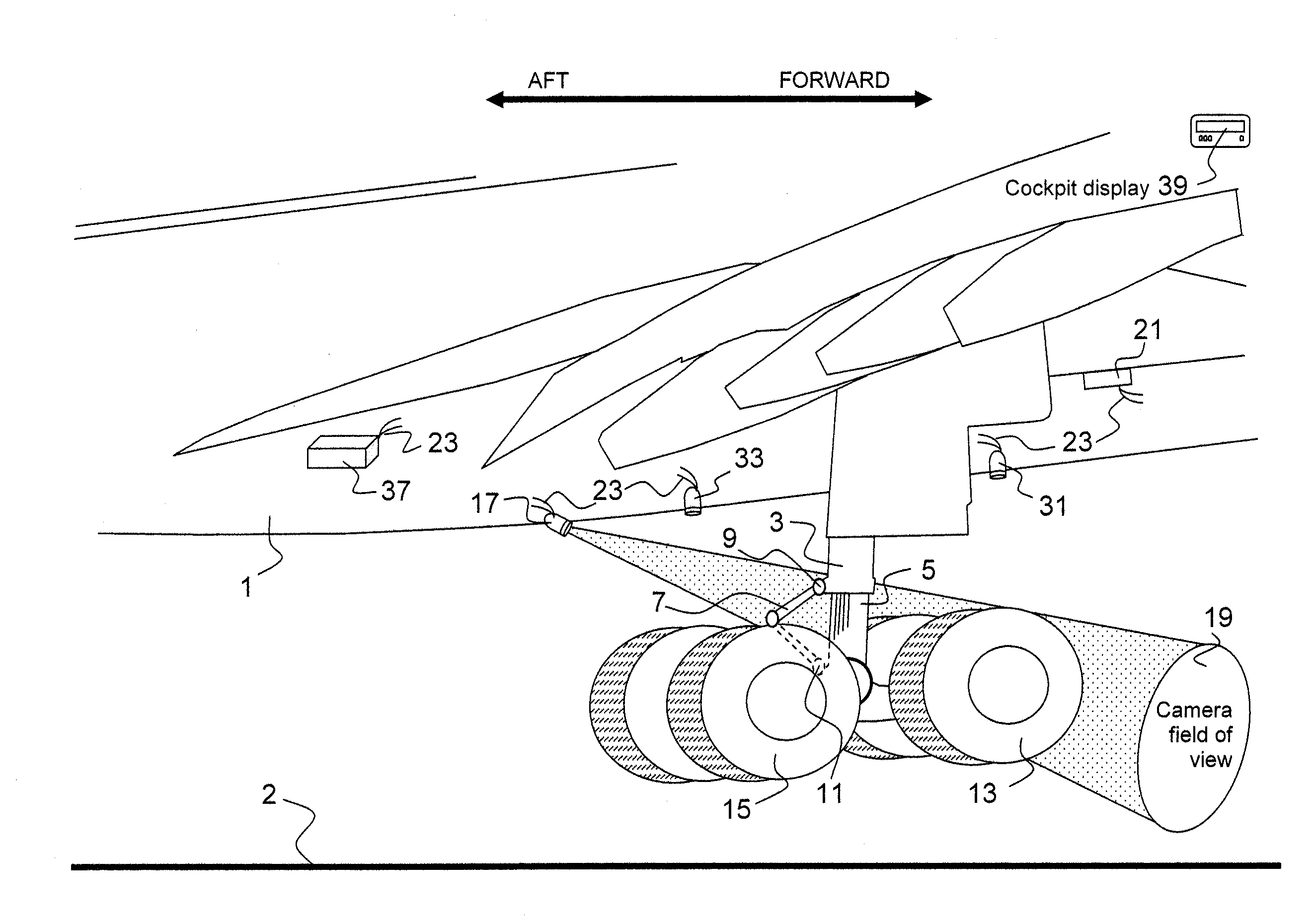
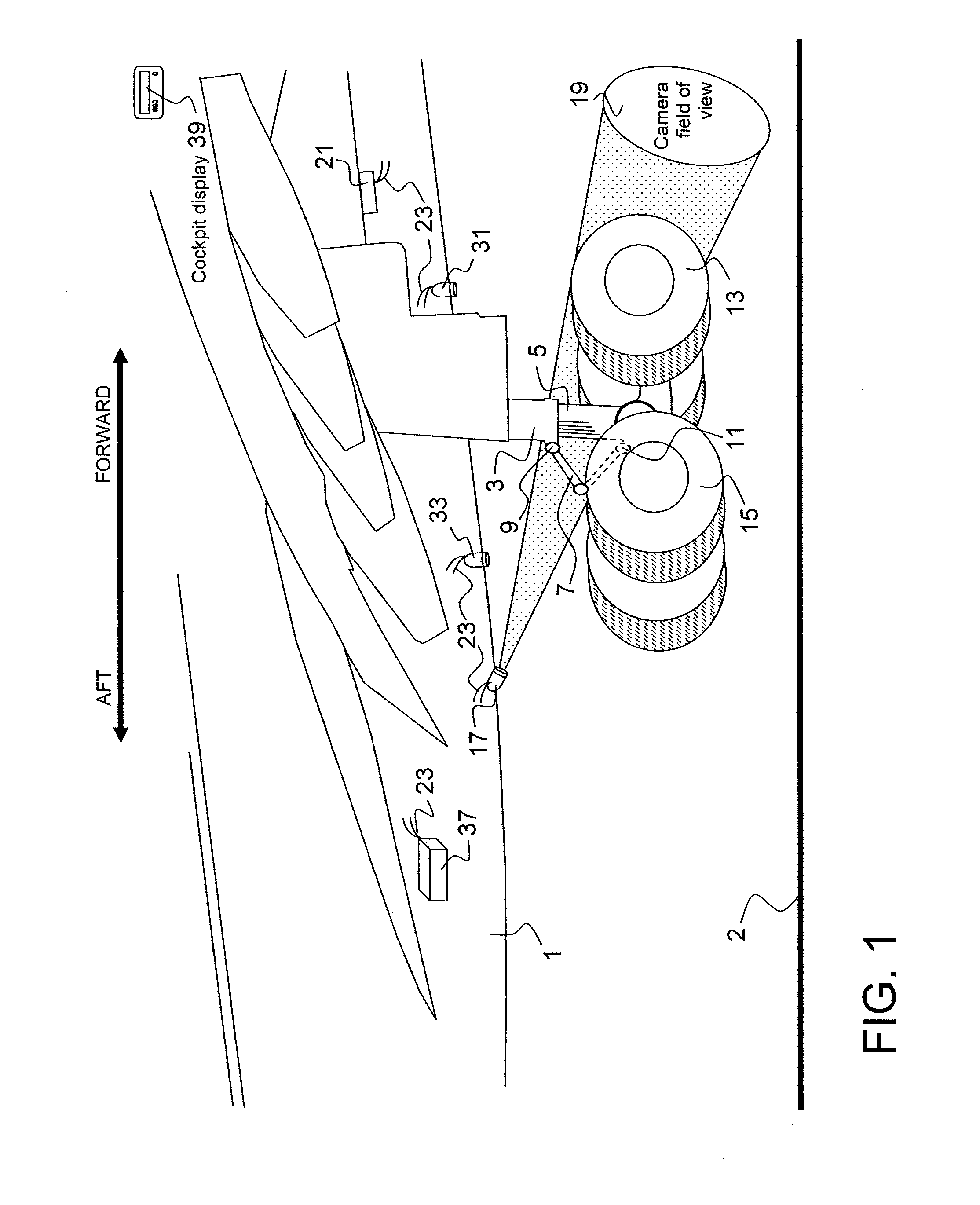
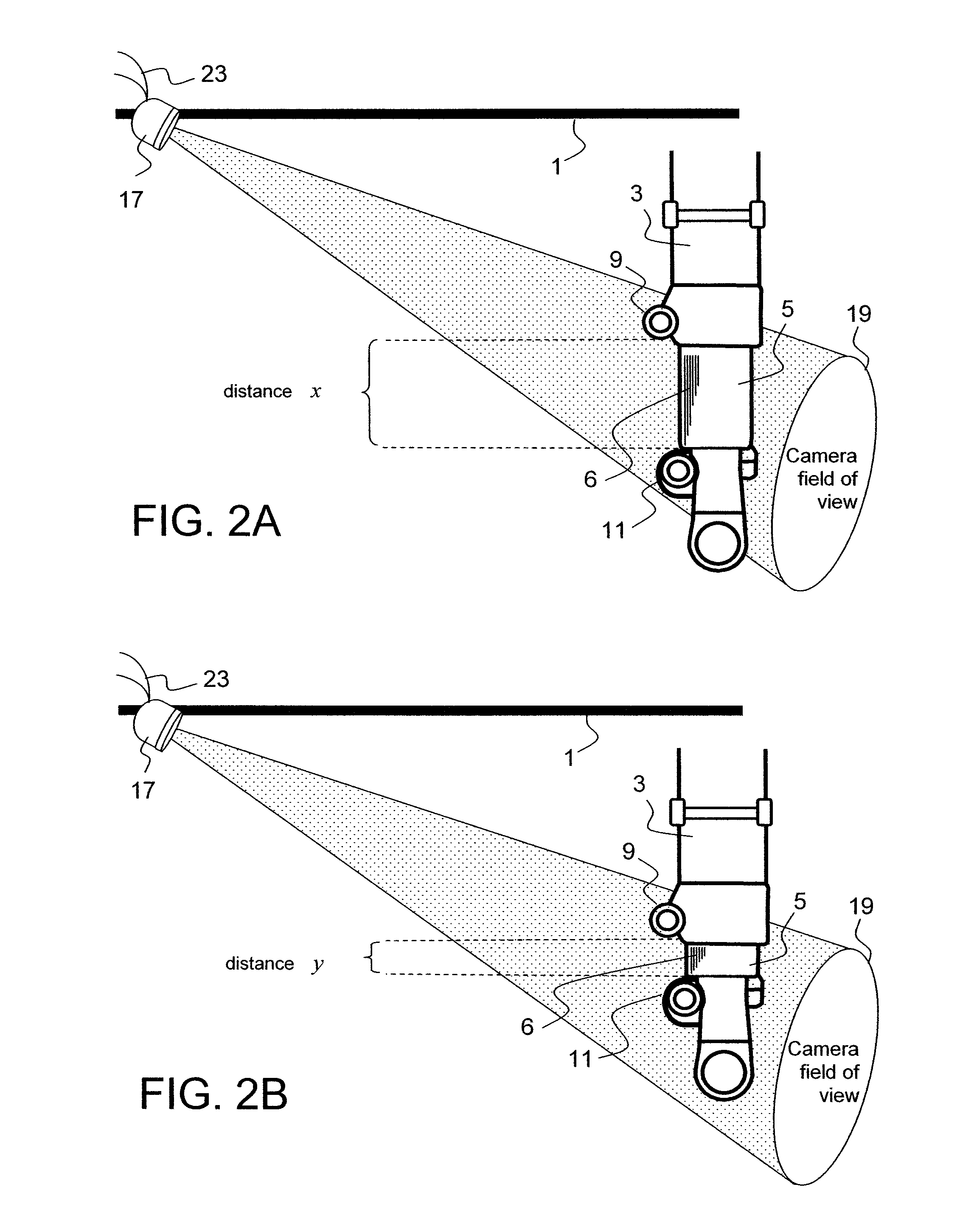
[0058]The present invention measures and determines the compression rate experienced by each landing gear strut on initial contact with the ground. The strut is monitored for compression so as to confirm that the aircraft has touched ground and also to determine the rate of strut compression and the descent velocity.

[0059]The present invention detects initial and continued movement of the landing gear strut by rapidly creating multiple digital photographs of the strut, prior to initial contact with the ground, as well as throughout the remainder of the landing event. The photographs are taken at a very rapid rate and are stored within a computer which is part of the system. The computer then compares the sequential photographs, maps the changes in strut configuration and compares the amount of strut changes in relation to elapsed time. Strut movement includes strut extension and compression.

[0060]The present invention works with telescoping strut designs and trailing arm strut desig...


PUM


Abstract

A system for use in monitoring, measuring, computing and displaying the rate of compression of aircraft landing gear struts experienced while aircraft are executing either normal or hard landing events. A high speed computer attached to high speed cameras, or range-finders, mounted in relation to each of the landing gear struts are used to monitor, measure and record the landing gear compression rates and aircraft touch-down vertical velocities experienced by landing gear struts, as the aircraft landing gear initially comes into contact with the ground. The system also determines through landing gear strut compression rates if aircraft landing limitations have been exceeded.

Description

BACKGROUND OF THE INVENTION[0001]An aircraft is typically supported by plural pressurized landing gear struts. Each landing gear strut is designed much like, and incorporates many of the features of, a typical shock absorber. Designs of landing gear incorporate moving components which absorb the impact force of landing. Moving components of an aircraft landing gear shock absorber are commonly telescopic elements. An alternate type of landing gear incorporates a trailing arm design which forms a triangle shape, where the main supporting body of the landing gear is hinged with a trailing arm, and a typical shock absorber functions as the third side of the triangle. The shock absorber of both types of landing gear comprise internal fluids, both hydraulic fluid and compressed nitrogen gas, and function to absorb the vertical descent forces generated when the aircraft lands.[0002]Aircraft have limitations regarding the maximum allowable force the aircraft landing gear and other supportin...

Claims


Application Information

Patent Timeline
IPC IPC(8): B64C25/00
CPCB64C25/00B64D45/0005B64D2045/008B64D2045/0085
Inventor NANCE, C. KIRK
Owner NANCE C KIRK
Why Eureka
Try Eureka