Supercharge Your Innovation With Domain-Expert AI Agents!

Objective lens drive and optical pickup apparatus

a technology of optical pickup and drive system, which is applied in the direction of data recording, dynamo-electric machines, dynamo-electric components, etc., can solve the problems of increasing cost, increasing the cost of drive force, and increasing the width of magnets, so as to reduce the effect of downsizing the size of the objective lens driv

Active Publication Date: 2012-02-07
SHARP KK
View PDF16 Cites 0 Cited by
  • Summary
  • Abstract
  • Description
  • Claims
  • Application Information

AI Technical Summary

Benefits of technology

This configuration enables a compact objective lens drive system that reduces size and cost while maintaining effective drive forces, enhancing the optical pickup apparatus's performance and efficiency.

Problems solved by technology

In the first and second related art, the magnet only used for the tilt coil is provided, therefore entailing a problem that the actuator is increased in size to secure a space required for the magnet, which causes an increase in cost, even if the magnet is not divided into the magnet parts with different polarities.
Furthermore, in the second related art, the drive force may be unstable depending on a displaceable position in the tracking direction.
In the third related art, the tracking coils are disposed on the opposite sides in the tracking direction, of the focus coil displaceable, and in order to secure displacement in the tracking direction, a problem arises that a magnet is inevitably large in width.
Furthermore, in such a configuration that the two tilt coils are laterally arranged in the tracking direction under the focus coil and that the moment generated by the respective tilt coils allows for movement driven in the tilt direction, it is hard to generate the drive force with small electricity due to the arrangement remote from a position of center of gravity of the lens holder.
Furthermore, in order to use the divided magnet to obtain the drive force in the focus direction, the magnet needs to have its width secured and therefore causes a problem of size increase in the tracking direction of the apparatus.

Method used


Image

  • Objective lens drive and optical pickup apparatus
  • Objective lens drive and optical pickup apparatus
  • Objective lens drive and optical pickup apparatus

Examples


first embodiment

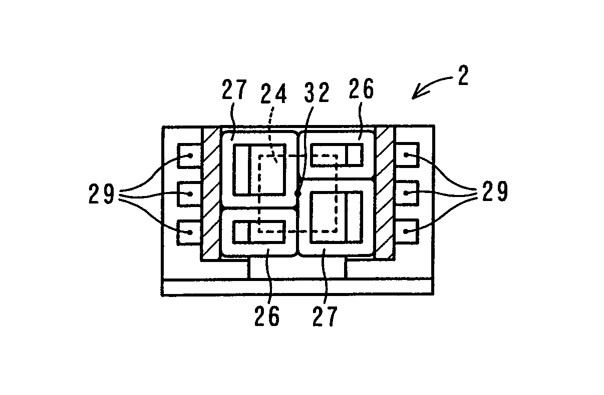
[0055]FIGS. 1A to 1C are views each showing a schematic configuration of an actuator 2 according to the invention. FIG. 1A is a top view, FIG. 1B a side view, and FIG. 1C a sectional view taken along cross-section line A-A shown in FIG. 1A.

[0056]The actuator 2 serving as an objective lens drive includes an objective lens 21, a lens holder 22, a base plate 23, magnets 24 and 25, tilt coils 26, tracking coils 27, a focus coil 28, elastic support members 29, and a support member 33. The objective lens 21 serving as a light-collecting unit collects a light beam onto a recording surface of a recording medium for recording information thereon, for example, an optical disk 11, and converts a light beam reflected by the recording surface into a collimated light beam. The objective lens 21 is disposed on an end of the lens holder 22.

[0057]The lens holder 22 serving as a holding unit is made of high-strength engineering plastic with an insulation property and high-specific strength, that is, ...

second embodiment

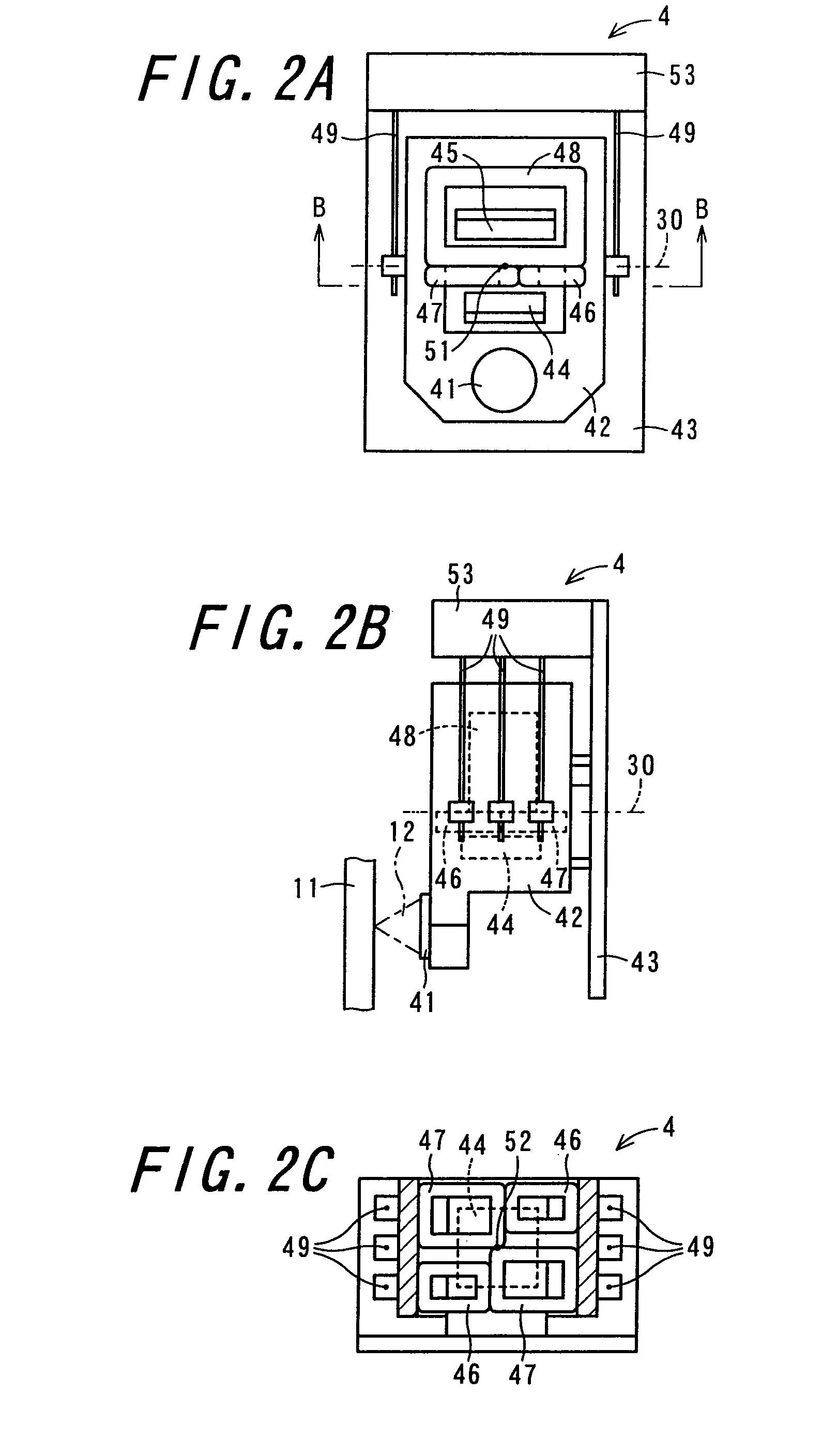
[0087]FIGS. 2A to 2C are views each showing a schematic configuration of an actuator 4 according to the invention. FIG. 2A is a top view, FIG. 2B a side view, and FIG. 2C a sectional view taken along cross-section line B-B shown in FIG. 2A.

[0088]The actuator 4 serving as an objective lens drive includes an objective lens 41, a lens holder 42, a base plate 43, magnets 44 and 45, tilt coils 46, tracking coils 47, a focus coil 48, elastic support members 49, and a support member 53.

[0089]The objective lens 41, the lens holder 42, the base plate 43, the magnets 44 and 45, the focus coil 48, the elastic support members 49, and the support member 53 are the same as the objective lens 21, the lens holder 22, the base plate 23, the magnets 24 and 25, the focus coil 28, the elastic support members 29, and the support member 33, respectively, shown in FIGS. 1A to 1C, and therefore will not be explained to avoid overlapping.

[0090]The tilt coils 46 and the tracking coils 47 are the same as the ...

third embodiment

[0096]FIGS. 3A to 3C are views each showing a schematic configuration of an actuator 6 according to the invention. FIG. 3A is a top view, FIG. 3B a side view, and FIG. 3C a sectional view taken along cross-section line C-C shown in FIG. 3A.

[0097]The actuator 6 serving as an objective lens drive includes an objective lens 61, a lens holder 62, a base plate 63, magnets 64, tilt coils 66, tracking coils 67, a focus coil 68, elastic support members 69, and a support member 73.

[0098]The objective lens 61, the lens holder 62, the base plate 63, the magnets 64, the tilt coils 66, the tracking coils 67, the focus coil 68, the elastic support members 69, and the support member 53 are the same as the objective lens 21, the lens holder 22, the base plate 23, the magnet 24, the tilt coils 26, the tracking coils 27, the focus coil 28, the elastic support members 29, and the support member 33, respectively, shown in FIGS. 1A to 1C, and therefore will not be explained to avoid overlapping. Note th...


PUM

PropertyMeasurementUnit
distanceaaaaaaaaaa
of symmetryaaaaaaaaaa
symmetryaaaaaaaaaa

Abstract

An objective lens drive and an optical pickup apparatus are provided which can be reduced in size. Two tilt coils and two tracking coils are disposed so that among planes defined by the respective coils, a plane perpendicular to a winding direction thereof is parallel to a reference plane defined on a lens holder at a predetermined reference distance or less, and are disposed at such positions as to be symmetrical to each other about a center of gravity of the lens holder. A focus coil is disposed so that among planes defined by the focus coil, a plane perpendicular to a recording surface of an optical disk is parallel to the reference plane at a predetermined reference distance or less relative to the two tilt coils and the two tracking coils.

Description

CROSS-REFERENCE TO RELATED APPLICATION[0001]This application claims priority to Japanese Patent Application No. 2007-284334, which was filed on Oct. 31, 2007, the contents of which are incorporated herein by reference in its entirety.BACKGROUND OF THE INVENTION[0002]1. Field of the Invention[0003]The present invention relates to a drive system for driving an objective lens and an optical pickup apparatus.[0004]2. Description of the Related Art[0005]FIGS. 5A to 5C are views each showing an actuator 40 according to a first related art. FIG. 5A is a top view, FIG. 5B a side view, and FIG. 5C a sectional view taken along cross-section line D-D shown in FIG. 5A. The actuator 40 is adapted to an optical pickup apparatus where an optical disk is used as a recording medium. In order to record or reproduce information on the optical disk 11, the actuator 40 includes a focus direction drive unit which controls a light beam 12 collected by an objective lens 401 to focus at an optimum position ...

Claims


Application Information

Patent Timeline
Patent Type & Authority Patents(United States)
IPC IPC(8): G11B7/00
CPCG11B7/0933G11B7/0935G11B7/0956
Inventor SAKO, SHINICHI
Owner SHARP KK
Features
  • R&D
  • Intellectual Property
  • Life Sciences
  • Materials
  • Tech Scout
  • Unparalleled Data Quality
  • Higher Quality Content
  • 60% Fewer Hallucinations
Learn More