Supercharge Your Innovation With Domain-Expert AI Agents!

Aperture controlling system

a technology of aperture driving circuit and control circuit, which is applied in the field of aperture controlling system, can solve the problems of inability to function properly, complicated circuits of ccds, and inability to include aperture driving circuits

Inactive Publication Date: 2012-03-27
HON HAI PRECISION IND CO LTD
View PDF2 Cites 0 Cited by
  • Summary
  • Abstract
  • Description
  • Claims
  • Application Information

AI Technical Summary

Benefits of technology

Enables effective control of the aperture in digital cameras equipped with CMOS sensors by converting digital signals into analog signals for motor control, allowing for proper adjustment of luminous flux, thereby overcoming the incompatibility issues with traditional CCD-based systems.

Problems solved by technology

As a result, the CCDs must include numerous complicated circuits.
However, if a CMOS is equipped in a camera instead of a CCD, the aperture driving circuit would not be able to function properly because the image signals output from the CMOS are digital video signals unsuitable for use in the original aperture driving circuit to control the aperture.

Method used


Image

  • Aperture controlling system
  • Aperture controlling system
  • Aperture controlling system

Examples


Embodiment Construction

[0010]Embodiments of the present disclosure will now be described in detail below and with reference to the drawings.

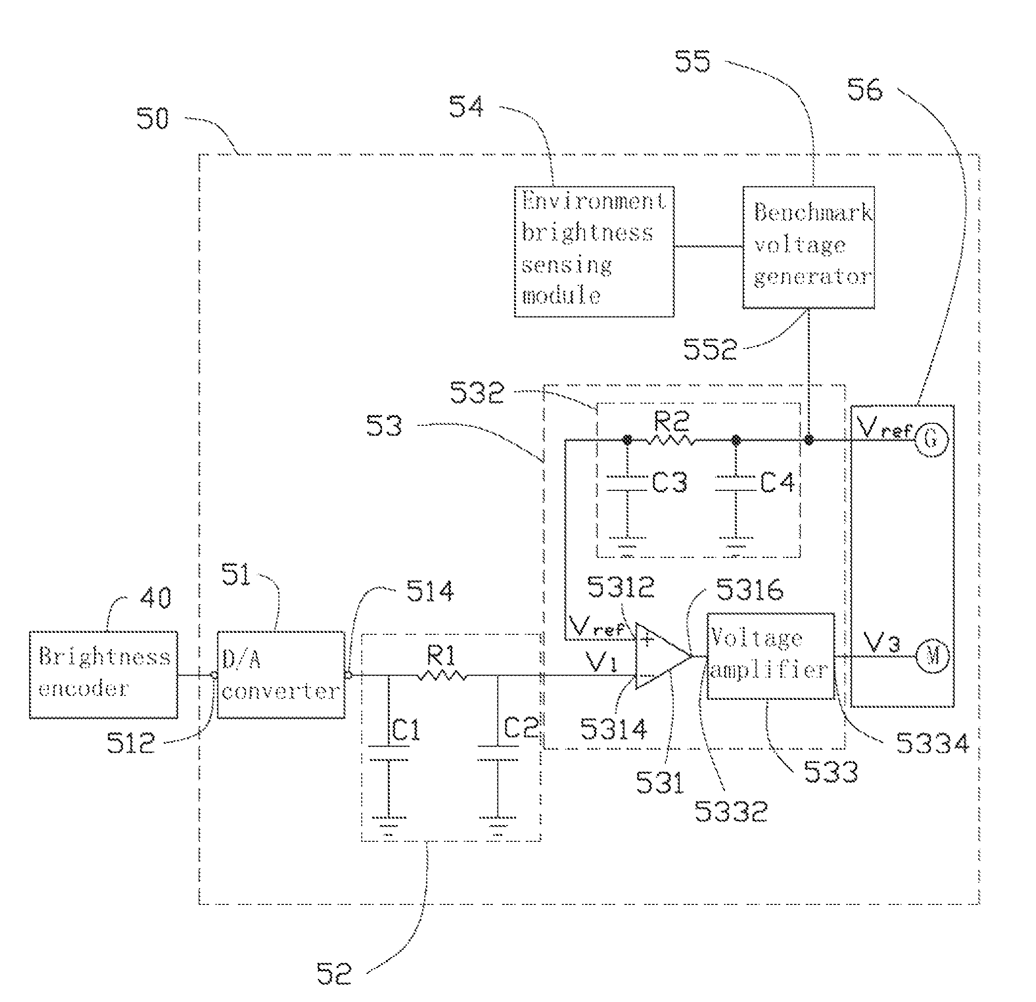
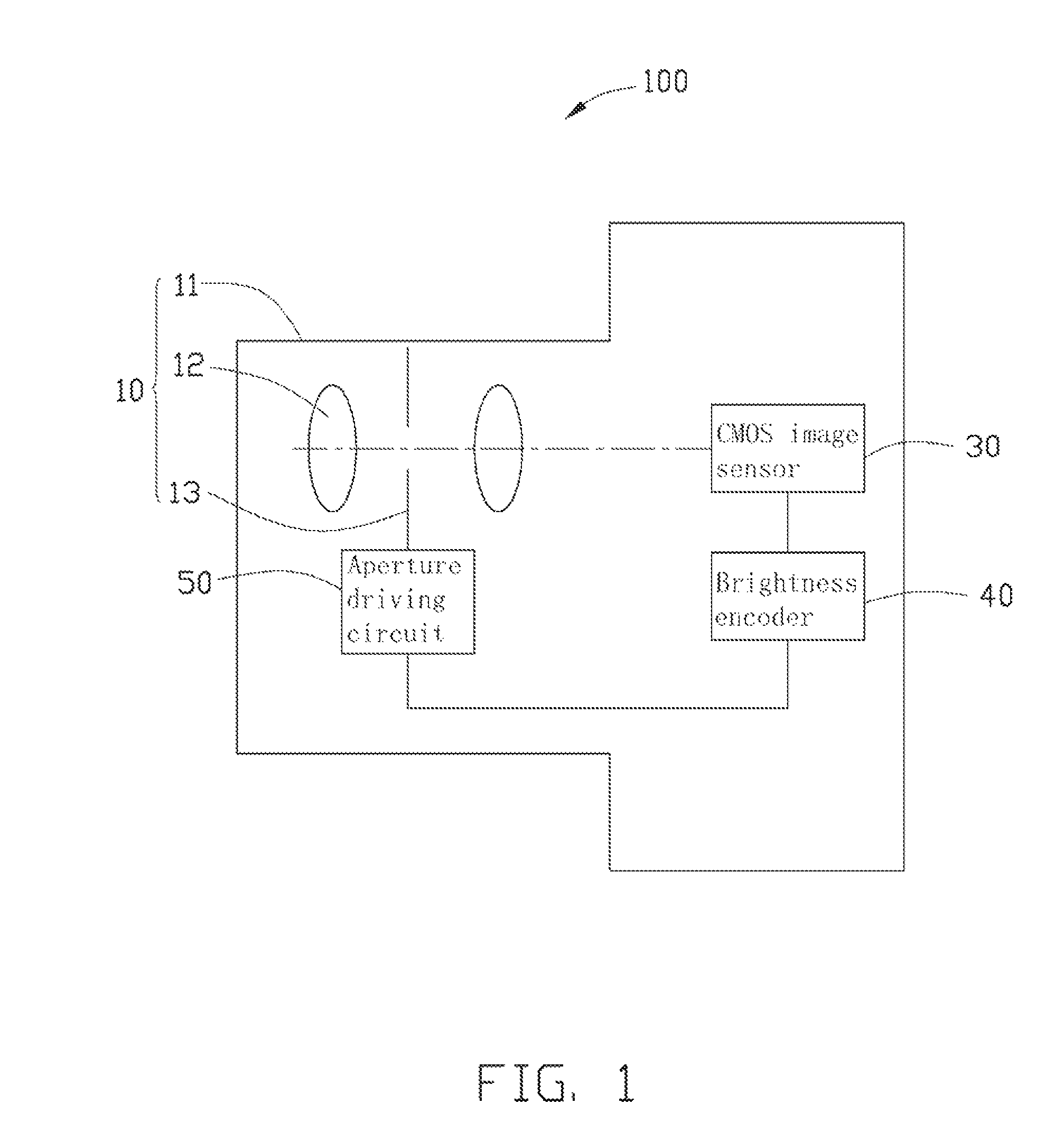
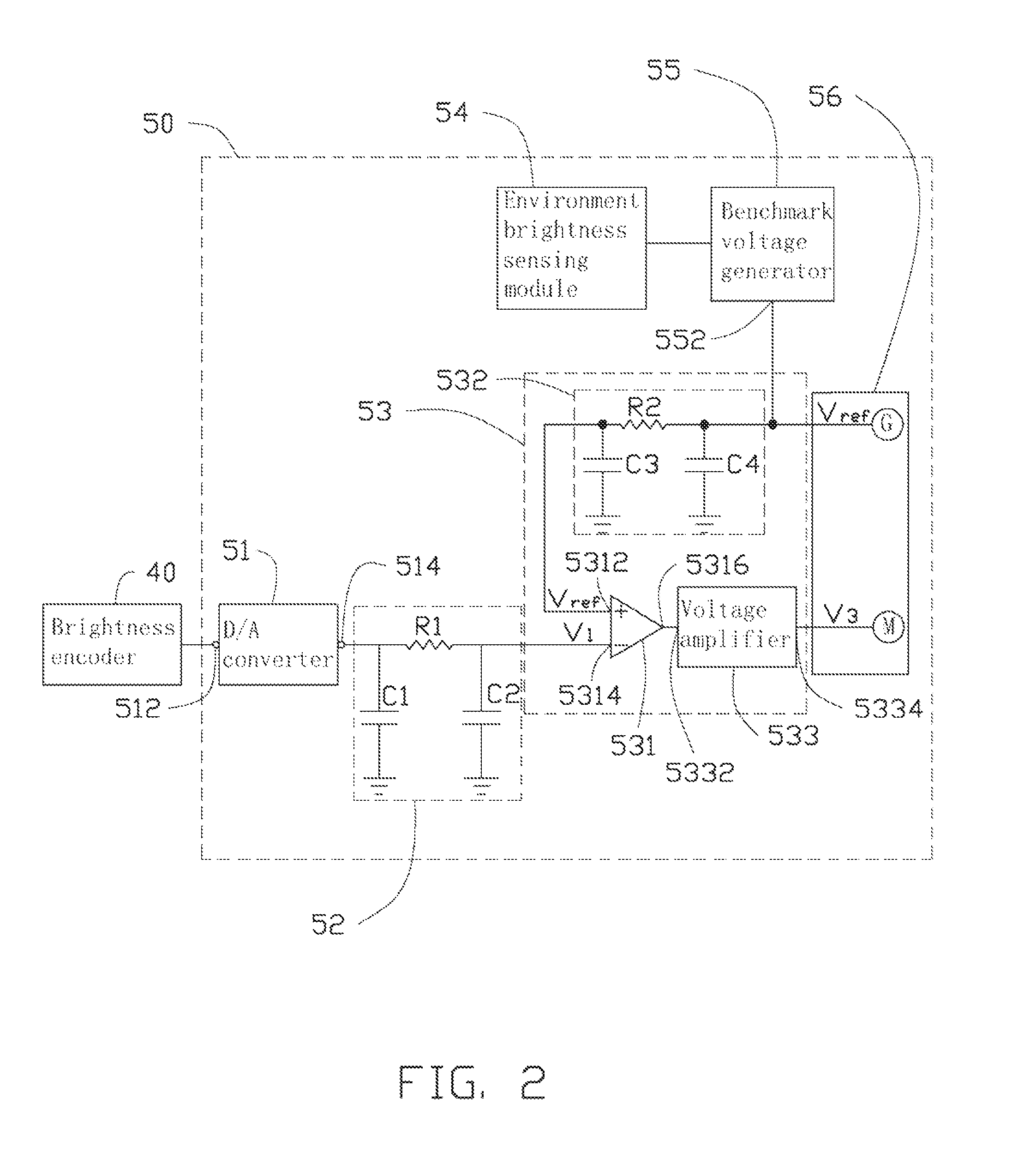
[0011]Referring to FIGS. 1-2, an aperture controlling system 100 according to an exemplary embodiment, includes a lens module 10, a complementary metal oxide semiconductor (CMOS) image sensor 30, a brightness encoder 40, and an aperture driving circuit 50. The lens module 10 aligns with the CMOS image sensor 30. The CMOS image sensor 30 is electrically coupled to the brightness encoder 40. The brightness encoder 40 is electrically coupled to the aperture driving circuit 50.

[0012]The lens module 10 includes a lens barrel 11, a number of lenses 12, and an aperture 13. Both the lenses 12 and the aperture 13 are received in the lens barrel 11. In the present embodiment, the aperture 13 is interposed between two adjacent lenses 12.

[0013]The CMOS image sensor 30 is configured to convert light signals received by the lens module 10 into digital electronic signals.

[0014]The b...


PUM


Abstract

An aperture controlling system includes a CMOS image sensor, a brightness encoder, an aperture and an aperture driving circuit. The brightness encoder is used for extracting brightness information sensed by the CMOS image sensor and converting the brightness information into digital codes. The aperture driving circuit includes a D / A converter, a motor coil driving circuit, an environment sensing module, a benchmark voltage generator and a motor. The motor is mechanically connected to the aperture. The motor coil driving circuit includes a voltage comparator. The input and the output of the D / A converter are respectively coupled to the brightness encoder and the inverting input of the voltage comparator. The input and the output of the benchmark voltage generator are respectively coupled to the environment sensing module and the non-inverting input of the voltage comparator. The output of voltage comparator is connected to the motor.

Description

BACKGROUND[0001]1. Technical Field[0002]The present disclosure relates to an aperture controlling system.[0003]2. Description of Related Art[0004]Most current digital cameras use Charge Coupled Devices (CCDs) to convert optical signals into electronic signals. However, the CCD must be supplied with 12 volts direct current to drive charges of each pixel of the CCD to move into an associated transmission channel. As a result, the CCDs must include numerous complicated circuits. As an alternative, Complementary Metal Oxide Semiconductor (CMOS) sensors, which are low-cost, low power consuming, and high integratable, become more and more favored by consumers.[0005]In general, an aperture of a digital camera is controlled by an aperture driving circuit that must use NTSC / PAL signals output from the CCD. However, if a CMOS is equipped in a camera instead of a CCD, the aperture driving circuit would not be able to function properly because the image signals output from the CMOS are digital ...

Claims


Application Information

Patent Timeline
Patent Type & Authority Patents(United States)
IPC IPC(8): G03B7/085
CPCG03B7/085
Inventor HSIEH, MING-CHIHCHEN, LIEN-HSUN
Owner HON HAI PRECISION IND CO LTD
Features
  • R&D
  • Intellectual Property
  • Life Sciences
  • Materials
  • Tech Scout
  • Unparalleled Data Quality
  • Higher Quality Content
  • 60% Fewer Hallucinations
Learn More