Check patentability & draft patents in minutes with Patsnap Eureka AI!

Mask health monitor using a faraday probe

a technology of faraday probe and mask health monitor, which is applied in the manufacture of final products, mass spectrometers, optical radiation measurement, etc., can solve the problems of adding an extra cost to solar cell production, non-uniform doping may occur, and using photoresis

Inactive Publication Date: 2012-04-24
VARIAN SEMICON EQUIP ASSOC INC
View PDF6 Cites 6 Cited by
  • Summary
  • Abstract
  • Description
  • Claims
  • Application Information

AI Technical Summary

Benefits of technology

This solution enables precise and cost-effective ion implantation with improved alignment and mask health monitoring, reducing the risk of non-uniform doping and increasing the efficiency of solar cell production by optimizing the ion beam alignment and mask condition.

Problems solved by technology

This does not allow precise doping of the various regions of the solar cell and, if voids, air bubbles, or contaminants are present, non-uniform doping may occur.
Ion implantation of solar cells, however, may require a certain pattern of dopants or that only certain regions of the solar cell substrate are implanted with ions.
Use of photoresist, however, would add an extra cost to solar cell production because extra process steps are involved.
Other hard masks on the solar cell surface likewise are expensive and require extra steps.

Method used


Image

  • Mask health monitor using a faraday probe
  • Mask health monitor using a faraday probe
  • Mask health monitor using a faraday probe

Examples


Embodiment Construction

[0027]The present invention will now be described more fully hereinafter with reference to the accompanying drawings, in which preferred embodiments of the invention are shown. This invention, however, may be embodied in many different forms and should not be construed as limited to the embodiments set forth herein. Rather, these embodiments are provided so that this disclosure will be thorough and complete, and will fully convey the scope of the invention to those skilled in the art. In the drawings, like numbers refer to like elements throughout.

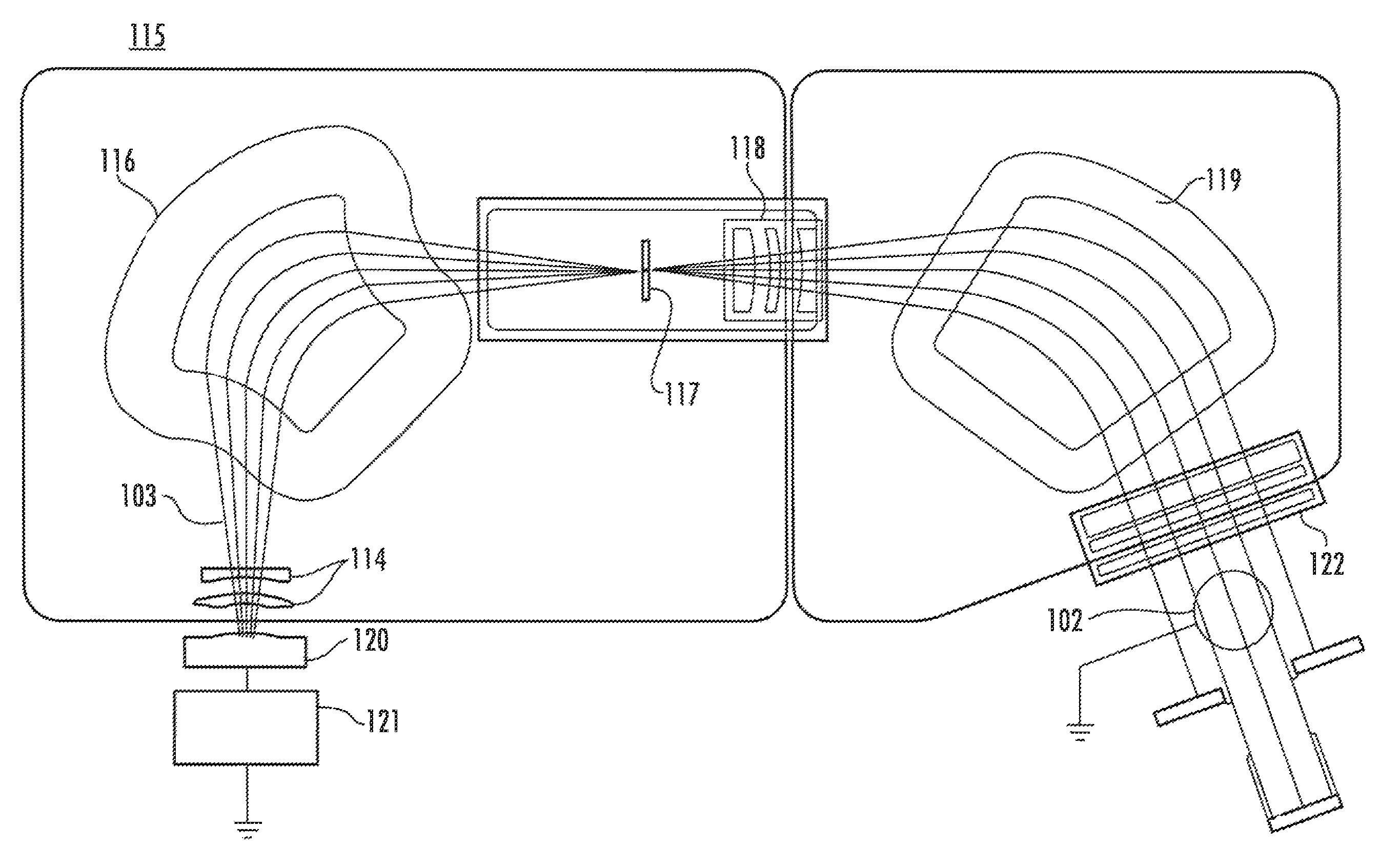
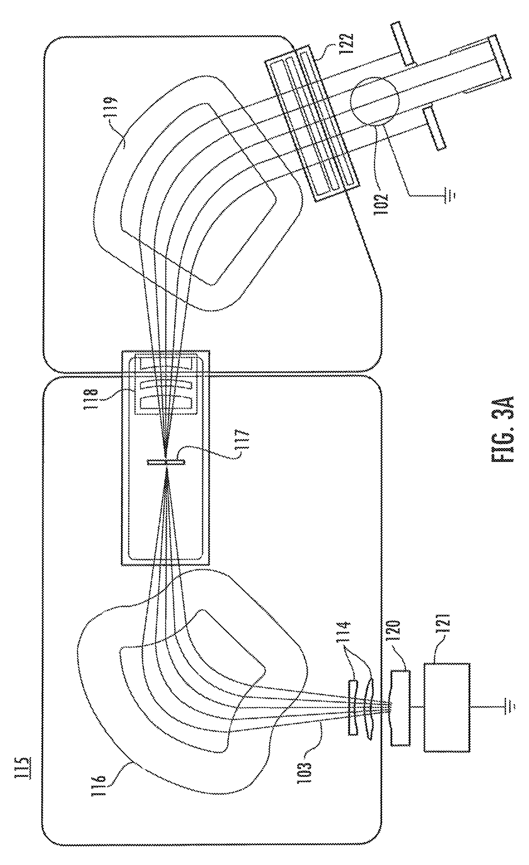
[0028]FIG. 3A is a block diagram of an ion implanter 115 including an ion source chamber 120. A power supply 121 supplies the required energy to source chamber 120 which is configured to generate ions of a particular species. The generated ions are extracted from the source through a series of electrodes 114 and formed into a beam 103 which passes through a mass analyzer magnet 116. The mass analyzer is configured with a particular magneti...


PUM


Abstract

In an ion implanter, an ion current measurement device is disposed behind a mask co-planarly with respect to a surface of a target substrate as if said target substrate was positioned on a platen. The ion current measurement device is translated across the ion beam. The current of the ion beam directed through a plurality of apertures of the mask is measured using the ion current measurement device. In this manner, the position of the mask with respect to the ion beam as well as the condition of the mask may be determined based on the ion current profile measured by the ion current measurement device.

Description

RELATED APPLICATIONS[0001]This patent application claims priority to U.S. Provisional Patent Application Ser. No. 61 / 229,852, filed Jul. 30, 2009 which is hereby incorporated by reference in its entirety.BACKGROUND OF THE INVENTION[0002]1. Field of the Invention[0003]Embodiments of the invention relate to the field of device fabrication. More particularly, the present disclosure relates to ion implantation through a mask and a device and system to monitor the health of the mask used during ion implantation.[0004]2. Discussion of Related Art[0005]Ion implantation is a standard technique for introducing conductivity-altering impurities into substrates. A precise doping profile in a substrate and associated thin film structure is critical for proper device performance. Generally, a desired impurity material is ionized in an ion source, the ions are accelerated to form an ion beam of prescribed energy, and the ion beam is directed at the surface of the substrate. The energetic ions in t...

Claims


Application Information

Patent Timeline
Patent Type & Authority Patents(United States)
IPC IPC(8): H01J37/317H01J3/07H01J37/244
CPCH01J37/3171H01L21/266H01L31/0288H01L31/0682H01L31/1804H01J2237/24507H01J2237/24528H01J2237/31711H01L21/26513Y02E10/547Y02P70/521H01L21/2658Y02P70/50H01J37/317
Inventor RIORDON, BENJAMIN B.BATEMAN, NICHOLAS P. T.WEAVER, WILLIAM T.LOW, RUSSELL J.
Owner VARIAN SEMICON EQUIP ASSOC INC
Features
  • R&D
  • Intellectual Property
  • Life Sciences
  • Materials
  • Tech Scout
  • Unparalleled Data Quality
  • Higher Quality Content
  • 60% Fewer Hallucinations
Learn More