Supercharge Your Innovation With Domain-Expert AI Agents!

Apparatus for attaching a device to a circular structure

a technology for attaching devices and circular structures, which is applied in the direction of furniture parts, instruments, signs, etc., can solve the problems of thermal expansion of pipes, inability to accurately indicate the time of flight data, and inability to use single metal clamp designs

Active Publication Date: 2012-05-29
BAKER HUGHES HLDG LLC
View PDF36 Cites 12 Cited by
  • Summary
  • Abstract
  • Description
  • Claims
  • Application Information

AI Technical Summary

Benefits of technology

[0009]An apparatus for attaching a device to a circular structure is disclosed. In one embodiment, the apparatus includes a clamp body attached to the outer surface of the circular structure using a strap, which can be attached to the clamp body using a spring that maintains an attachment force to prevent movement of the clamp body over a wide range of temperatures and temperature cycling of the circular structure and the strap. In one embodiment, the device can be installed in the clamp body and coupled to the outer surface of the circular structure using one or more spring washers that maintain an attachment force between the device and the outer surface of the circular structure to prevent detachment of the device from the outer surface of the circular structure over a wide range of temperatures and temperature cycling of the circular structure.

Problems solved by technology

For example, if the probe remains coupled to the outer surface of the pipe but moves along the outer surface of the pipe from one location to another, this can lead to inaccurate results based on the comparison of data from two different locations on the outer surface of the pipe.
Similarly, if the probe becomes decoupled from the outer surface of the pipe or the coupling force between the probe and the outer surface of the pipe changes, this can result to inaccurate results based on the comparison of data from different coupling positions on the outer surface of the pipe or different coupling forces.
For instance, if the probe was not properly coupled to the outer surface of the pipe, this could lead to inaccurate time of flight data that would fail to accurately indicate the amount of corrosion / erosion at a location of the pipe.
In some cases, the decoupling could be so significant that it would prevent the ability of the probe to transmit the ultrasonic pulse through the pipe wall to conduct any testing.
Also, given the configuration of the existing metal clamp, a single metal clamp design can typically only be used to accommodate one or two probes on the circumference of the outer surface of the pipe at a particular location (e.g., on the top and bottom of the pipe, but not on the sides, or on the left side and right side of the pipe, but not on the top and bottom).
While this existing bolt or U-bolt metal clamp is capable in some cases of ensuring that the position and coupling of the probe in relation to the outer surface of the pipe remain fixed and unchanged over time, there can be circumstances where this is not the case.
), the pipe can be heated to this high temperature, resulting in thermal expansion of the pipe (i.e., increase in the outer diameter of the pipe), which may bend or otherwise deform the clamp body or U-bolts / bots of the existing metal clamp.
In addition, if the pipe is heated to this high temperature, the existing metal clamp, which is in contact with the outer surface of the pipe, can also be heated to this high temperature, making the existing metal clamp more malleable and likely to bend or otherwise deform.
In some cases, the temperature cycling may be so significant over time that the probe becomes decoupled from the outer surface of the pipe, requiring that the existing metal clamp be removed and replaced in a laborious process.
In order to minimize temperature cycling, the size and thickness of the existing metal clamp can be significantly increased, which increases the difficulty of handling and installing the clamp and undesirably increases the weight of the clamp on the pipe.

Method used


Image

  • Apparatus for attaching a device to a circular structure
  • Apparatus for attaching a device to a circular structure
  • Apparatus for attaching a device to a circular structure

Examples


Embodiment Construction

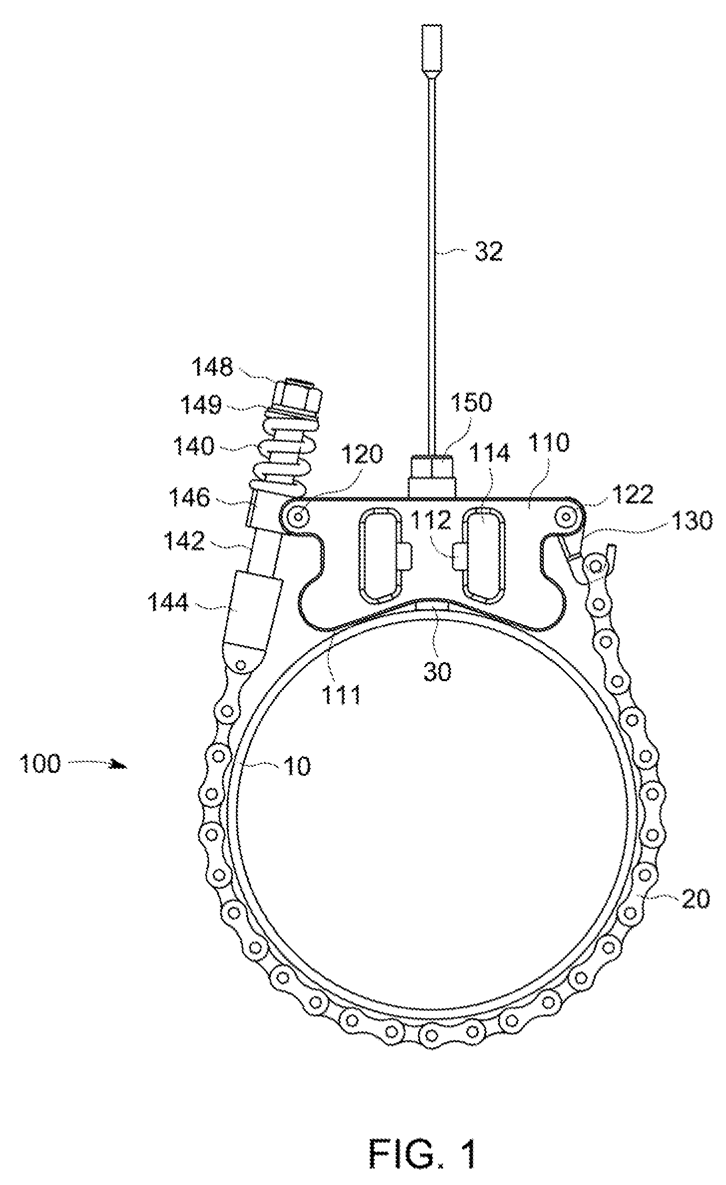
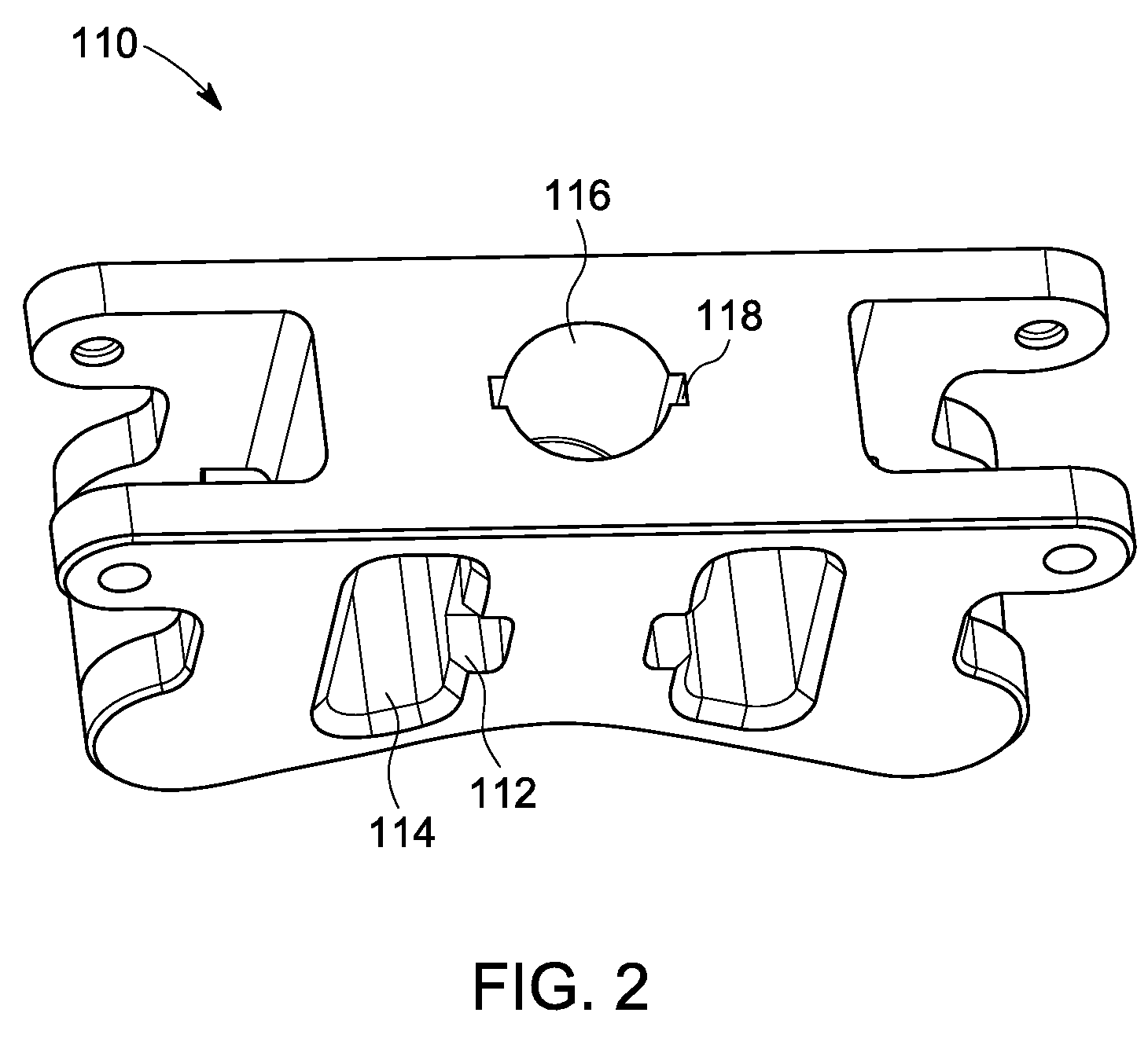
[0015]FIG. 1 shows a clamp 100 for attaching (e.g., coupling) a probe 30 to the outer surface of a pipe 10 (e.g., having an outer diameter of 10″ (254 mm)) in an exemplary embodiment of the invention. Although the exemplary embodiment of the clamp is shown coupling a probe 30 to the outer surface of a pipe 10, the clamp 100 can be used to attach a variety of devices to a variety of circular structures besides probes 30 or other nondestructive testing devices, and besides pipes (e.g., other conduits, poles, etc.). As shown in FIG. 1, the probe 30 and associated probe wire 32 can be installed within a clamp body 110, which can couple the probe 30 to the outer surface of the pipe 10. In one embodiment, the clamp body 110 can include a clamp body opening 116 (e.g., a hole) to receive and hold the probe 30 against the outer surface of the pipe 10. The probe 30 can be coupled to the outer surface of the pipe 10 through an acoustically conductive foil (not shown) (e.g., a gold foil) or oth...


PUM


Abstract

An apparatus for attaching a device to a circular structure is disclosed. In one embodiment, the apparatus includes a clamp body attached to the outer surface of the circular structure using a strap, which can be attached to the clamp body using a spring that maintains an attachment force to prevent movement of the clamp body over a wide range of temperatures and temperature cycling of the circular structure and the strap. In one embodiment, the device can be installed in the clamp body and coupled to the outer surface of the circular structure using one or more spring washers that maintain an attachment force between the device and the outer surface of the circular structure to prevent detachment of the device from the outer surface of the circular structure over a wide range of temperatures and temperature cycling of the circular structure.

Description

BACKGROUND OF THE INVENTION[0001]The subject matter disclosed herein relates to an apparatus for attaching a device to the outer surface of a circular structure, and more particularly, to an apparatus for coupling a nondestructive testing device to the outer surface of a pipe.[0002]Several industries (e.g., oil and gas, refinery, chemical, power generation) require the transport of fluid (e.g., liquids or gases) through pipes. Nondestructive testing devices can be placed on the outer surface of these pipes to monitor corrosion / erosion of the pipes, including corrosion / erosion on the interior of pipe walls. In many cases, the probe or other nondestructive testing device is permanently coupled to the outer surface of the pipe at a single location to continuously monitor corrosion / erosion at that location to determine pipe corrosion / erosion rates and to determine whether that pipe location is in need of preventative maintenance to prevent a pipe failure.[0003]One example of a nondestru...

Claims


Application Information

Patent Timeline
Patent Type & Authority Patents(United States)
IPC IPC(8): F16M11/00
CPCF16L41/008G01N29/223G01N2291/044G01N2291/2634
Inventor LUO, WEIMAYER, TOUNINECHOI, JAE
Owner BAKER HUGHES HLDG LLC
Features
  • R&D
  • Intellectual Property
  • Life Sciences
  • Materials
  • Tech Scout
  • Unparalleled Data Quality
  • Higher Quality Content
  • 60% Fewer Hallucinations
Learn More