Supercharge Your Innovation With Domain-Expert AI Agents!

Method and an arrangement for controlling pump displacement in a work vehicle

a technology for controlling the displacement of the pump and the work vehicle, which is applied in the direction of mechanical equipment, couplings, constructions, etc., can solve the problems of engine failure, engine failure, and difficulty in finding an engine that precisely manages the desired power output, so as to reduce the amount of hydraulic work, reduce the load of the engine, and reduce the effect of machine productivity

Active Publication Date: 2012-06-12
VOLVO CONSTR EQUIP AB
View PDF8 Cites 2 Cited by
  • Summary
  • Abstract
  • Description
  • Claims
  • Application Information

AI Technical Summary

Benefits of technology

This approach effectively relieves engine load, preventing stalling and maintaining machine productivity by proportionally controlling pump displacement based on operational conditions, ensuring the hydraulic system operates efficiently even at low engine speeds.

Problems solved by technology

It is difficult to find an engine that exactly manages the desired power outputs at different engine speeds.
The problem with different output power demand is particularly pronounced at low engine speeds.
If the driver utilizes the power from the engine at low engine speeds to drive the vehicle's half shafts at the same time as the hydraulic system is activated, then there is a risk that the engine will cut out or that the engine will “stick”, that is it will not be able to increase the engine speed when the driver depresses the accelerator pedal.
The driver can, of course, adjust the power consumption via various controls, when he senses a loss of engine speed, but this can be problematical, particularly when the engine suddenly cuts out.
Further, even skilled drivers overcompensate and therefore unnecessarily reduce the amount of hydraulic work the hydraulic system is truly capable of performing.
As a result, machine productivity is reduced.
Preferably, the maximum available pump displacement is limited to a larger extent upon a smaller magnitude of the detected operational condition.

Method used


Image

  • Method and an arrangement for controlling pump displacement in a work vehicle
  • Method and an arrangement for controlling pump displacement in a work vehicle
  • Method and an arrangement for controlling pump displacement in a work vehicle

Examples


first embodiment

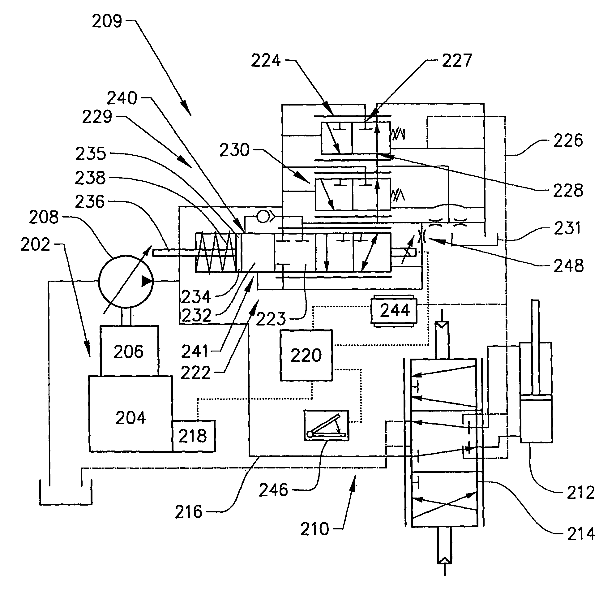
[0056]According to the invention, the power source operational condition detection means 218 is adapted for detecting a torque or output power of the power source. In this embodiment, the engine torque is sensed. The pressure in a clutch in the transmission may be used as a measure of the engine torque. Such clutch pressure signals are directly related to the torque being transmitted by the clutch to the wheels and by the wheels to the ground. When the torque falls to a predetermined minimum, the controller 220 will output a signal with a level as a function of accessible engine torque. As an alternative, the controller 220 will output a signal with a level as a function of both accessible engine torque and the detected position of an accelerator pedal 246.

second embodiment

[0057] the engine speed is sensed by the detection means 218. When the engine speed falls to a predetermined minimum, the controller 220 will output a signal with a level as a function of the detected engine speed. As an alternative, the controller 220 will output a signal with a level as a function of both the detected engine speed and the detected position of an accelerator pedal 246.

[0058]The engine speed sensor may be a magnetic pick-up device sensitive to the movement of a gear tooth in the engine, which is proportional to crankshaft speed.

[0059]According to a variant of the first and second embodiments, a limit value for a minimum engine speed is set. This limit value defines the critical region, in which the maximum available pump displacement is controlled. Further, within this established critical region, the detected torque or output power of the power source is used to control the level of the maximum available pump displacement.

[0060]According to a specific example, the ...

third embodiment

[0061] a turbocharger is operatively connected to the engine. The turbocharger pressure is sensed. When the turbocharger pressure falls to a predetermined minimum, the controller 220 will output a signal with a level as a function of the detected turbocharger speed. As an alternative, the controller will output a signal with a level as a function of both the detected turbocharger pressure and the detected position of an accelerator pedal 246.

[0062]The control arrangement 209 further comprises means 244 for detecting a hydraulic pressure associated to the actuator 212 and generating a corresponding signal. The pressure detection means 244 is adapted to sense the pressure in the load-sensing pressure conduit 226. According to an alternative, the pressure detection means 244 is adapted to sense the pressure in the conduit 216 delivering hydraulic fluid to the actuator 212. The controller 220 is adapted to receive the pressure signal and comprises means for comparing the detected hydrau...


PUM


Abstract

A method of controlling a work vehicle includes detecting an operational condition of a powertrain which is adapted to propel the vehicle, wherein a power source in the powertrain is adapted to operatively drive at least one variable displacement pump, wherein the pump is adapted to operatively drive at least one hydraulic actuator via hydraulic fluid for moving a work implement and / or steering the vehicle. The method further includes comparing the detected operational condition with a predetermined critical condition, limiting a maximum available displacement of the pump and thereby establishing an available pump displacement range if the magnitude of the detected operational condition is within the predetermined critical condition, detecting a hydraulic load associated to the actuator, and adjusting the pump displacement of the pump in response to the detected hydraulic load within the available pump displacement range.

Description

BACKGROUND AND SUMMARY[0001]The present invention relates to a method and an arrangement for controlling pump displacement in a work vehicle.[0002]The term “work vehicle” comprises different types of material handling vehicles like construction machines, such as a wheel loader, an articulated hauler, a backhoe loader, a motor grader and an excavator. Further terms frequently used for work vehicles are “earth-moving machinery” and “off-road work machines”. The invention will be described below in a case in which it is applied in a wheel loader. This is to be regarded only as an example of a preferred application. The work vehicles are for example utilized for construction and excavation work, in mines etc.[0003]The work vehicle comprises a powertrain for propelling the vehicle. A power source, preferably an internal combustion engine, and especially a diesel engine, is adapted to provide the power for propelling the vehicle.[0004]The work vehicle further comprises a hydraulic system....

Claims


Application Information

Patent Timeline
Patent Type & Authority Patents(United States)
IPC IPC(8): F15B11/16F15B11/042
CPCE02F9/2232E02F9/2235E02F9/2296F15B2211/20523F15B2211/20553F15B2211/6313F15B2211/633F15B2211/6346F15B2211/6652
Inventor PALO, MARKKU
Owner VOLVO CONSTR EQUIP AB
Features
  • R&D
  • Intellectual Property
  • Life Sciences
  • Materials
  • Tech Scout
  • Unparalleled Data Quality
  • Higher Quality Content
  • 60% Fewer Hallucinations
Learn More