Valve-type oil feeder
a valve-type, oil-feeding technology, applied in the direction of machines/engines, machines/engines, distribution equipment, etc., can solve the problems of high failure rate, high machining accuracy, and difficult repair work, so as to improve detection accuracy, improve working condition, and facilitate the delivery of lubricant oil or grease
- Summary
- Abstract
- Description
- Claims
- Application Information
AI Technical Summary
Benefits of technology
Problems solved by technology
Method used
Image

Examples
embodiment 1
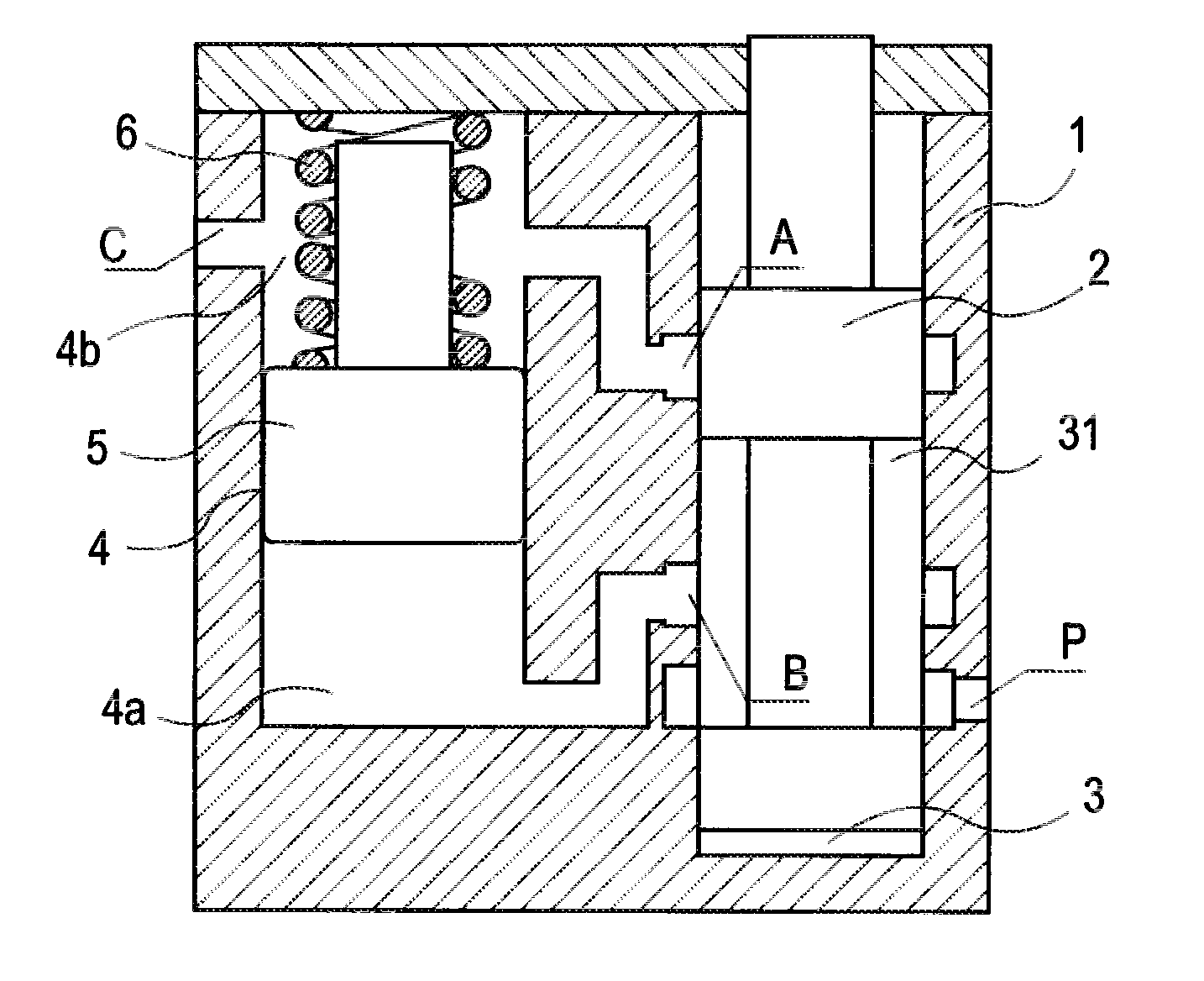
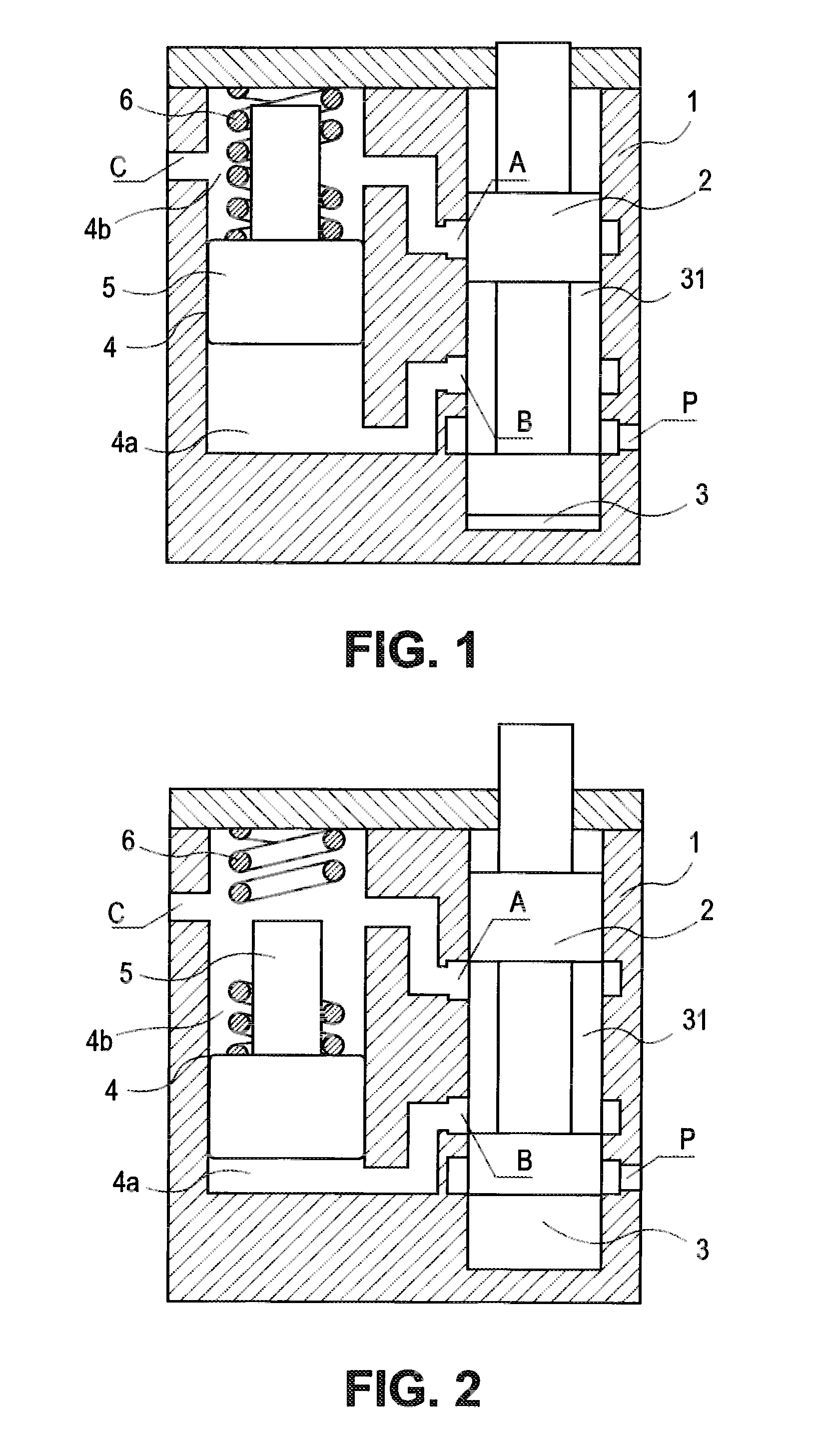
[0026]FIG. 1 is a structural schematic view of the valve-type oil feeder in working state in accordance with the first embodiment of the present invention. FIG. 2 is a structural schematic view of the valve-type oil feeder in original state in accordance with the first embodiment of the present invention.
[0027]As shown in FIG. 1 and FIG. 2, the valve-type oil feeder in accordance with the first embodiment of the present invention mainly comprises a housing 1, a valving spindle 2, and a piston 5.
[0028]The housing 1 has a valve chamber 3 designed to accommodate the valving spindle 2, and a piston chamber 4 designed to accommodate the piston 5. The valve chamber 3 has an oil inlet P, a first outlet A, and a second outlet B. In addition, the valve chamber 3 further has an oil storage chamber 31. The piston chamber 4 has an oil intake chamber 4a, an oil discharge chamber 4b, and an oil outlet C. The oil intake chamber 4a communicates with the second outlet B, and the oil discharge chambe...
embodiment 2
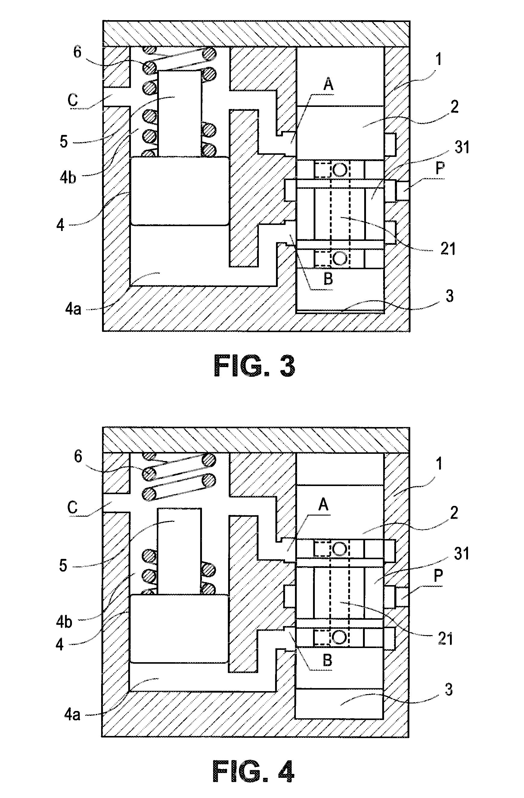
[0039]FIG. 3 is a structural schematic view of the valve-type oil feeder in working state in accordance with the second embodiment of the present invention. FIG. 4 is a structural schematic view of the valve-type oil feeder in original state in accordance with the second embodiment of the present invention.
[0040]As shown in FIG. 3 and FIG. 4, the difference between the valve-type oil feeder in the second embodiment and the valve-type oil feeder in the first embodiment of the present invention mainly lies only in the structure of the valve chamber 3 and the structure of the valving spindle 2 in the valve chamber 3. Therefore, hereunder the valve chamber 3 and the valving spindle 2 in the valve chamber 3 will be mainly described. Generally, the description about other aspects of the first embodiment is also applicable to the second embodiment essentially, and therefore will not be further detailed here. In addition, unless otherwise stated, the description about all aspects of the fir...
embodiment 3
[0043]FIG. 5 is a structural schematic view of the valve-type oil feeder in working state in accordance with the third embodiment of the present invention. FIG. 6 is a structural schematic view of the valve-type oil feeder in original state in accordance with the third embodiment of the present invention.
[0044]As shown in FIG. 5 and FIG. 6, the difference between the third embodiment and the first and second embodiments mainly lies in the structure of the valve chamber. In addition, it is noted that, in the third embodiment, the valving spindle 2 is arranged in the valve chamber 3 in a rotary manner.
[0045]Specifically, as shown in FIG. 5 and FIG. 6, the valving spindle 2 has a groove 32 on a side, and has a radial through hole 22 arranged therein. In addition, the groove 32 and the radial through hole 22 are arranged at a predetermined angle to each other on the circumference of the valving spindle 2, i.e., they are staggered by a predetermined angle to each other, for example, stag...
PUM
 Abstract
Description
Claims
Application Information
 - R&D
- Intellectual Property
- Life Sciences
- Materials
- Tech Scout
- Unparalleled Data Quality
- Higher Quality Content
- 60% Fewer Hallucinations
Browse by: Latest US Patents, China's latest patents, Technical Efficacy Thesaurus, Application Domain, Technology Topic, Popular Technical Reports.
© 2025 PatSnap. All rights reserved.Legal|Privacy policy|Modern Slavery Act Transparency Statement|Sitemap|About US| Contact US: help@patsnap.com