Check patentability & draft patents in minutes with Patsnap Eureka AI!

Intake system for internal combustion engine

a technology for internal combustion engines and intake manifolds, which is applied in the direction of combustion-air/fuel-air treatment, air intakes for fuel, machines/engines, etc., can solve the problems of tuning the engine, undesirable power output decline, and disturbance of air/fuel control, so as to reduce the amount of gasket materials used in the engine, the effect of reducing design complexity and material cos

Inactive Publication Date: 2012-07-17
FORD GLOBAL TECH LLC
View PDF20 Cites 17 Cited by
  • Summary
  • Abstract
  • Description
  • Claims
  • Application Information

AI Technical Summary

Benefits of technology

This solution minimizes gasket material usage, reduces design complexity and cost, and maintains engine performance without degrading power output, as demonstrated by computer simulations and dynamometer data.

Problems solved by technology

Although external leaks may adversely impact engine control because an external vacuum leak will likely cause unmetered air to be introduced into the engine's cylinders, thereby disturbing the air / fuel control, unwanted cross-talk between adjacent cylinder runners may very well upset the tuning of the engine, causing an undesirable decrement in power output.
Unfortunately, this use of material merely for the purpose of preventing cross-talk between adjacent cylinders is costly and adds to the complexity of the gasket design.
Moreover, this issue exists with other induction system joints, such as the joint between an upper intake manifold and a lower intake manifold.

Method used


Image

  • Intake system for internal combustion engine
  • Intake system for internal combustion engine
  • Intake system for internal combustion engine

Examples


Embodiment Construction

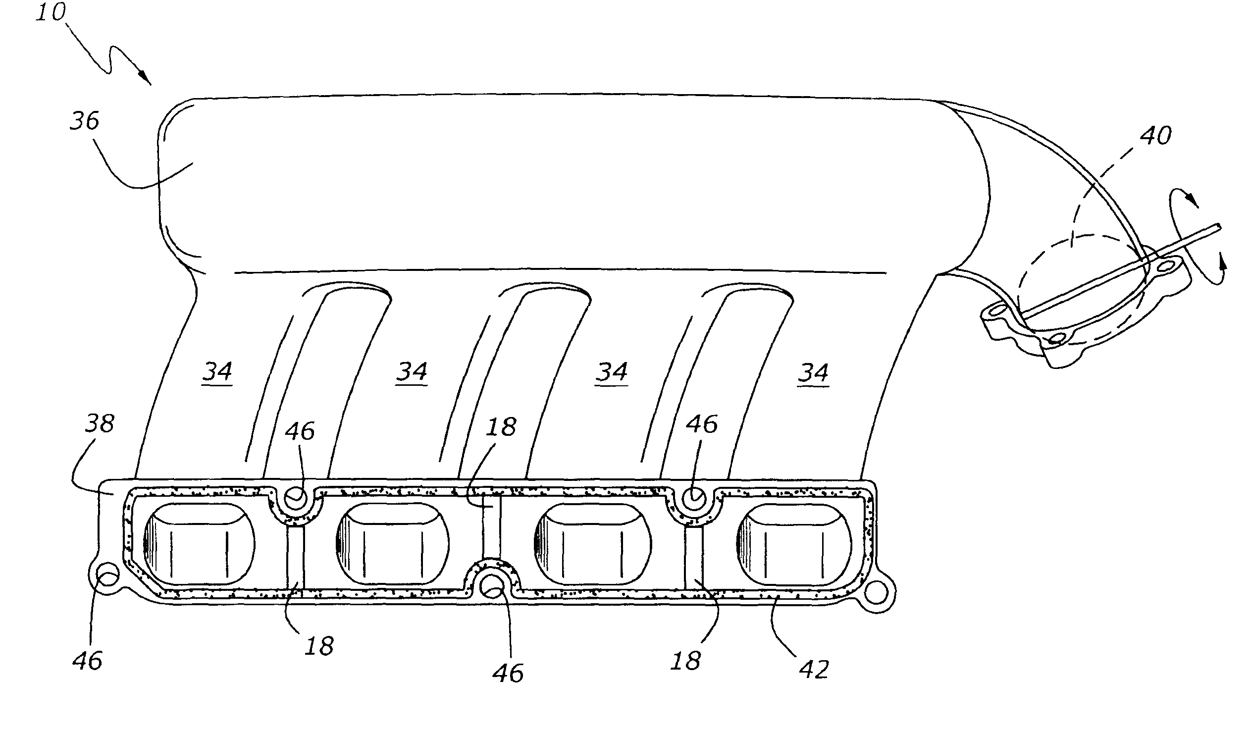
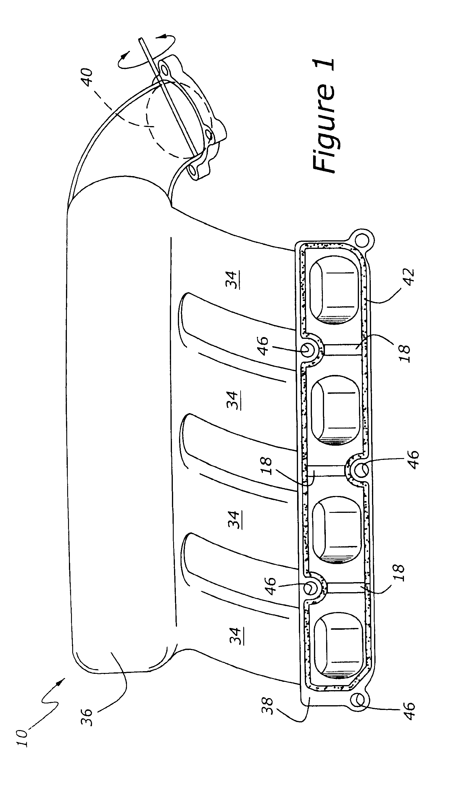
[0016]As shown in FIG. 1, intake manifold 10 includes a throttle valve, 40, leading to a plenum, 36, from which several runners, 34, extend to a mounting flange, 38. Intake manifold 10 may be configured as either an upper intake manifold which is used in conjunction with a lower intake manifold, or as a standalone intake manifold useable without the necessity of a lower intake manifold. Mounting flange 38 has a number of fastener apertures, 46, which allow the attachment of intake manifold 10 to a cylinder head of an engine. FIG. 1 also shows a perimeter gasket region, 42, which extends about the outer periphery of mounting flange 38. It is noted that perimeter gasket region 42 does not extend between adjacent runners 34 of intake manifold 10. Rather, FIG. 1 shows a first embodiment, in which a number of projecting tongue elements, 18, are molded upon mounting flange 38. These projecting tongue elements 18 cooperate with a number of grooved receptacle elements 26 formed in cylinder ...


PUM

PropertyMeasurementUnit
perimeteraaaaaaaaaa
plastic moldingaaaaaaaaaa
pressureaaaaaaaaaa

Abstract

An intake system for an internal combustion engine includes a cylinder head and an intake manifold attached to the cylinder head. A labyrinth seal is interposed between the intake manifold and the cylinder head, with the labyrinth seal including a projection formed in one of the intake manifold and cylinder head, and a mating receptacle formed in the other of the intake manifold and a cylinder head.

Description

BACKGROUND OF THE INVENTION[0001]1. Field of the Invention[0002]The present invention relates to an intake manifold and cylinder head for an internal combustion engine, and more specifically to a sealing system for use between an intake manifold mounting flange and a cylinder head of the engine. The present invention is equally applicable for sealing an upper intake of an engine to a lower intake.[0003]2. Related Art[0004]Intake manifolds are typically mounted to the cylinder heads of internal combustion engines with detailed gasketing intended to prevent not only leaks of outside air into the engine's cylinders, but also to prevent pressure pulses in one intake runner from interacting with the pressure pulses in an adjacent intake runner. Although external leaks may adversely impact engine control because an external vacuum leak will likely cause unmetered air to be introduced into the engine's cylinders, thereby disturbing the air / fuel control, unwanted cross-talk between adjacent...

Claims


Application Information

Patent Timeline
Patent Type & Authority Patents(United States)
IPC IPC(8): F02M35/10F02F1/42
CPCF02M35/10078F02M35/112F02M35/10347F02M35/10321
Inventor GUPTA, NATHAN
Owner FORD GLOBAL TECH LLC
Features
  • R&D
  • Intellectual Property
  • Life Sciences
  • Materials
  • Tech Scout
  • Unparalleled Data Quality
  • Higher Quality Content
  • 60% Fewer Hallucinations
Learn More