Supercharge Your Innovation With Domain-Expert AI Agents!

Lubrication device for gas engine

a technology for lubricating devices and gas engines, which is applied in the direction of machine/engine, lubrication of auxiliaries, and crankcase compression engine lubrication, etc., can solve the problems of intake air valves, exhaust gas valves (stem guide) wear, and the intake air valve seat as well as the exhaust gas valve seat wear

Active Publication Date: 2012-08-14
MITSUBISHI HEAVY IND MEIKI ENGINES CO LTD
View PDF14 Cites 3 Cited by
  • Summary
  • Abstract
  • Description
  • Claims
  • Application Information

AI Technical Summary

Benefits of technology

[0029]According to the above disclosure of the present invention, the gas engine is provided with the lubrication device thereby a valve gear room is formed on a cylinder head of the engine, the lubrication device comprising:
[0030]a blow-by gas entrance pipe through which the blow-by gas generated in the gas engine flows into the valve gear room, and
[0031]a blow-by gas discharge pipe through which the blow-by gas flowing into the valve gear room is discharged;
[0033]an oil mist separator is arranged at the downstream side of the blow-by gas discharge pipe, the oil mist separator separating the drain oil and the air in the blow-by gas;
[0034]the outlet regarding the drain oil from the oil mist separator communicates with an oil discharge device through an oil pipe, the an oil discharge device being arranged at an upstream side of an air fuel-gas mixer mixing the fuel gas with the intake air for the engine, the upstream being in relation to the intake air;
[0035]the outlet regarding the air from the oil mist separator communicates with an air inlet of the air cleaner for the engine intake air, through a breathing pipe.

Problems solved by technology

In a case of a gas engine in comparison with a gasoline, the wear of the intake air valve (stem) guide as well as the exhaust gas valve (stem) guide becomes larger; further, the wear of the intake air valve seat as well as the exhaust gas valve seat becomes larger.

Method used


Image

  • Lubrication device for gas engine
  • Lubrication device for gas engine
  • Lubrication device for gas engine

Examples


Embodiment Construction

[0056]Hereafter, the present invention will be described in detail with reference to the embodiments shown in the figures. However, the dimensions, materials, shape, the relative placement and so on of a component described in these embodiments shall not be construed as limiting the scope of the invention thereto, unless especially specific mention is made.

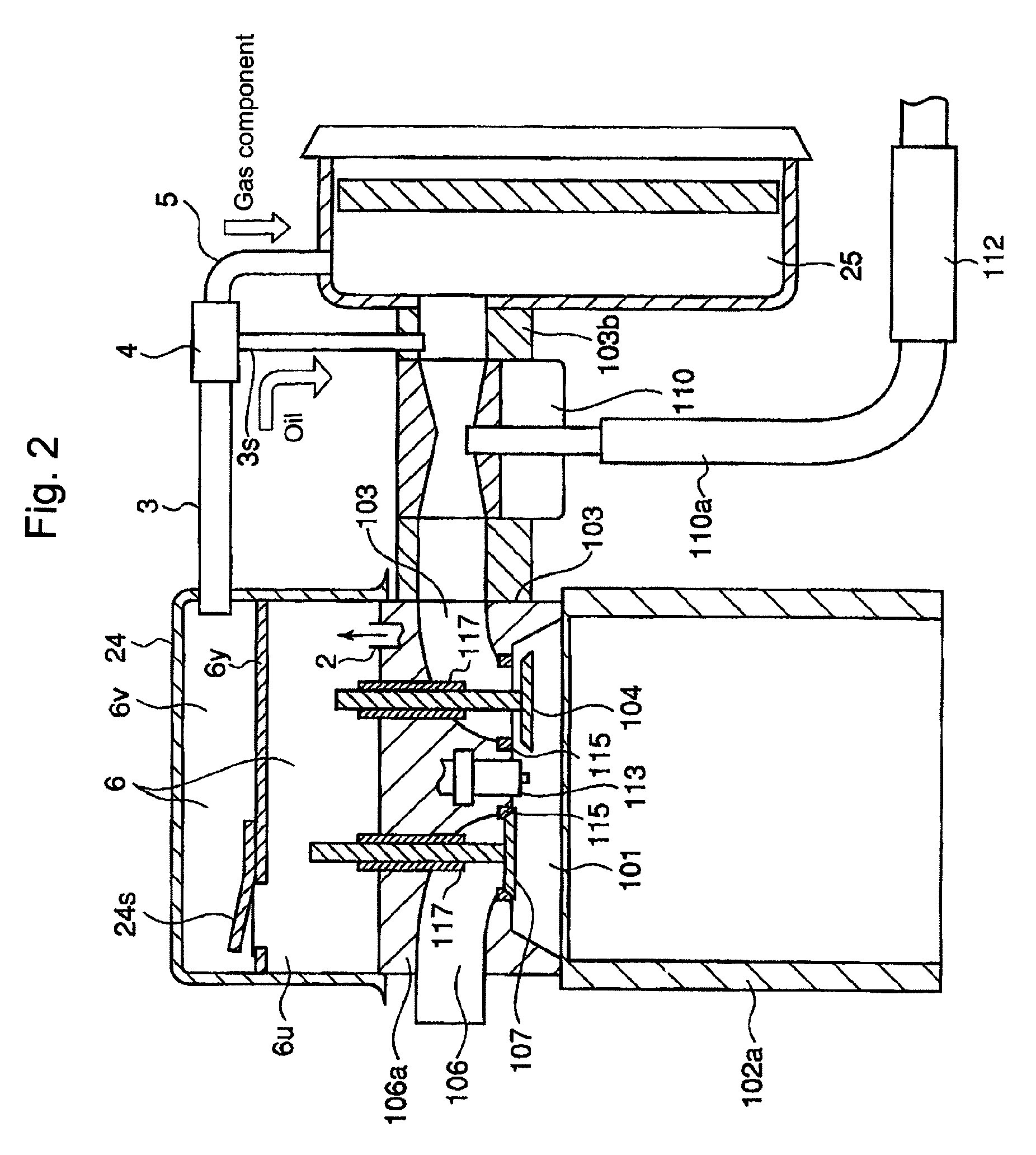
[0057]FIG. 1(A) shows the configuration of a gas engine around the combustion chamber thereof, according to an embodiment of the present invention; FIG. 1(B) shows an enlargement of the part Z in FIG. 1(A); FIG. 2 shows the configuration as to FIG. 1(A), according to the embodiment of the present invention; FIG. 3 shows an A-A cross-section of FIG. 1(A), according to the embodiment of the present invention; FIG. 4 shows an enlargement of an oil mist separator, according to the embodiment of the present invention.

[0058]In FIGS. 1(A) and 1(B) and FIG. 2, an engine (a gas engine) denoted by the numeral 100 is a four-stroke cycle gas ...


PUM


Abstract

Providing a gas engine in which the drain oil in the blow-by gas as a lubricant is mixed into the air fuel-gas mixture, the lubricant actively lubricating the bearing surfaces of the wear parts such as the valve seats and valve guides as to the intake-air valve and the exhaust gas valve, so that the lubricating device improves the engine lubricating conditions. A lubrication device for a gas engine thereby a valve gear room 6 is formed on a cylinder head, including: a blow-by gas discharge pipe 3 through which the blow-by gas flowing into the valve gear room 6 is discharged; whereby, an oil mist separator 4 is arranged at the downstream side of the blow-by gas discharge pipe, the oil mist separator separating the drain oil and the air in the blow-by gas; the outlet regarding the drain oil from the oil mist separator communicates with an oil discharge device 1 through an oil pipe 3s, the an oil discharge device being arranged at an upstream side of a gas mixer 110 mixing the fuel gas with the intake air for the engine, the upstream being in relation to the intake air; the outlet regarding the air from the oil mist separator communicates with an air inlet of the air cleaner 25 for the engine intake air, through a breathing pipe 5.

Description

FIELD OF THE INVENTION[0001]The present invention relates to a lubricating device for a gas engine that is provided with a valve gear room that is formed above a cylinder head.BACKGROUND OF THE INVENTION[0002]FIG. 5 shows an outline configuration of a lubricating system around an air intake device and a valve gear device as to a general gas engine.[0003]In FIG. 5, the engine that is depicted with the numeral 100 is a four-stroke cycle gas-engine provided with a spark plug 113; thereby, the engine comprises a cylinder liner 102a in which a piston (not shown in FIG. 5) is guided so as to perform reciprocating movements, and a combustion chamber 101 that is formed below the undersurface of a cylinder head 106a, over the top surface of the piston, inside the inner surface of the cylinder liner 102a. [0004]Further, the engine 100 comprises an intake-air port 103 that communicate with the combustion chamber 101, an intake-air valve 104 that opens and closes so as to control the intake air...

Claims


Application Information

Patent Timeline
Patent Type & Authority Patents(United States)
IPC IPC(8): F01M13/04
CPCF01M3/02F01M3/04F01M9/10F01M13/00F01M13/022F01M13/0416F01M2013/0438
Inventor MARUSHIMA, HIROYOSHISAKAGUCHI, MAKOTOTANIOKA, DAISUKE
Owner MITSUBISHI HEAVY IND MEIKI ENGINES CO LTD
Features
  • R&D
  • Intellectual Property
  • Life Sciences
  • Materials
  • Tech Scout
  • Unparalleled Data Quality
  • Higher Quality Content
  • 60% Fewer Hallucinations
Learn More