Supercharge Your Innovation With Domain-Expert AI Agents!

Printed wiring board feed-through capacitor

a technology of wire wires and capacitors, applied in the direction of feed-through capacitors, fixed capacitor details, fixed capacitors, etc., can solve the problems of difficult to make ceramic discs large enough for capacitors for high-power circuits, and no generally accepted method for applying feed-through capacitors to a circuit, etc., to achieve high capacitance, easy integration into circuits, and high power

Active Publication Date: 2012-12-04
HAMILTON SUNDSTRAND CORP
View PDF18 Cites 0 Cited by
  • Summary
  • Abstract
  • Description
  • Claims
  • Application Information

AI Technical Summary

Benefits of technology

This solution provides a sturdy, cost-effective, and versatile feed-through capacitor capable of handling high power and high current applications, with increased reliability and flexibility in design, suitable for industrial use.

Problems solved by technology

In high power applications, and particularly high current applications, there is no generally accepted method for applying feed-through capacitors to a circuit.
Because ceramics are brittle by nature, it is difficult to make ceramic discs large enough for use in capacitors for high power circuits.

Method used


Image

  • Printed wiring board feed-through capacitor
  • Printed wiring board feed-through capacitor
  • Printed wiring board feed-through capacitor

Examples


Embodiment Construction

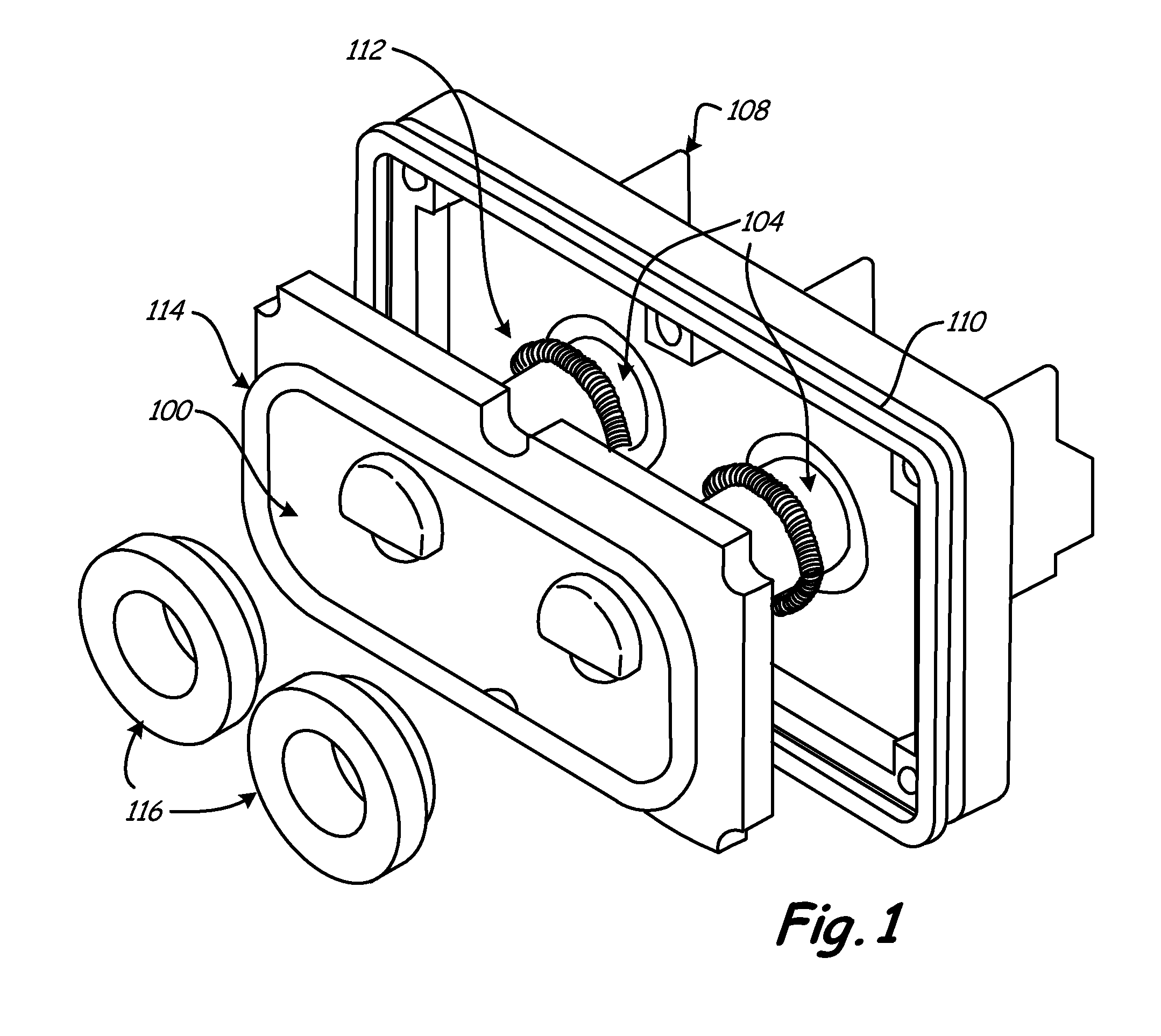
[0013]FIG. 1 shows an embodiment of the invention. Capacitor 100 is constructed in a printed wiring board. Terminal studs 104 pass through openings in capacitor 100. Capacitor 100 attaches to terminal block 108. Gasket seal 110 and stud contact spring 112 facilitate connection between terminal block 108 and capacitor 100. Chassis contact spring 114 and stud boot seals 116 are located on the underside of capacitor 100 and facilitate connection with the chassis (not shown).

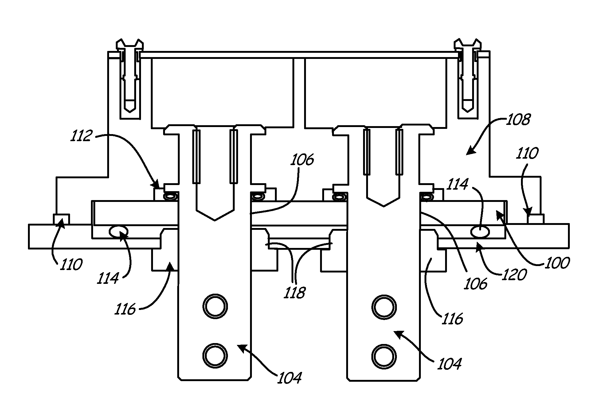
[0014]FIG. 2 is a cross-sectional view of the assembled components shown in FIG. 1. In FIG. 2, capacitor 100 is fit into position against terminal block 108. Terminal stud 104 passes through openings 106 in capacitor 100 and openings 118 in chassis wall 120. Stud boot seals 116 seal the opening of the studs 104 through wall 120. Capacitor 100 is held in place by sandwiching between wall 120 and terminal block 108 floated on contact springs 112 and 114. Terminal block 108 is held to wall 120 by fasteners (not shown)....


PUM


Abstract

A feed-through capacitor is constructed in a printed wiring board using alternating layers of metal capacitive layers and plastic dielectric layers of the printed wiring board. The large number of layers, the avoidance of ceramic layers and the flexible geometry of this device allow it to be used in many applications, particularly in those involving high power high current. Also, because it utilizes a printed wiring board, the capacitor can be made in numerous sizes and shapes.

Description

STATEMENT OF GOVERNMENT INTEREST[0001]This invention was made with Government support under contract no. N0019-02-C-3002 awarded by the Department of the Navy. The Government has certain rights in this invention.BACKGROUND OF THE INVENTION[0002]A feed-through capacitor connects to a conductive shaft or stud that passes through a chassis wall, and it filters unwanted high-frequency electromagnetic interference from an electrical circuit. A feed-through capacitor may be used on either an input or output conductor, and it prevents electromagnetic interference from getting into or out of the circuit. Feed-through capacitors are generally positioned close to a connection interface in order to isolate the connection from electromagnetic interference.[0003]Feed-through capacitors are connected from a conductor to the chassis of a device and they provide a path for high frequency current to flow from the conductor to the chassis. In a typical feed-through capacitor, a capacitive element sur...

Claims


Application Information

Patent Timeline
Patent Type & Authority Patents(United States)
IPC IPC(8): H01G4/35H01G4/228H01G4/236H01G4/08H01G4/30
CPCH01G4/35H05K1/162H05K3/429H05K2201/09672H05K2201/10303
Inventor DOLFI, EUGENE W.METZLER, MARK W.LUKAN, MARK C.CARTER, ERIC A.
Owner HAMILTON SUNDSTRAND CORP
Features
  • R&D
  • Intellectual Property
  • Life Sciences
  • Materials
  • Tech Scout
  • Unparalleled Data Quality
  • Higher Quality Content
  • 60% Fewer Hallucinations
Learn More