Check patentability & draft patents in minutes with Patsnap Eureka AI!

Centrifugal dehydrating device for mop

a centrifugal dehydrating and mop technology, which is applied in the direction of carpet cleaners, lighting and heating apparatus, separation processes, etc., can solve the problems of labor-saving and stable operation of the dehydrating device, and achieve the effects of stable operation, long service life and high speed

Inactive Publication Date: 2012-12-11
TSAI YAO FENG
View PDF14 Cites 18 Cited by
  • Summary
  • Abstract
  • Description
  • Claims
  • Application Information

AI Technical Summary

Benefits of technology

[0008]By such an arrangement, water is prevented from entering the one-way bearing, providing a longer service life. Furthermore, operation of the dehydrating device is stable and labor-saving. Further, the rotary container can rotate at a high speed while providing operating convenience and enhanced efficiency.

Problems solved by technology

Furthermore, operation of the dehydrating device is stable and labor-saving.

Method used


Image

  • Centrifugal dehydrating device for mop
  • Centrifugal dehydrating device for mop
  • Centrifugal dehydrating device for mop

Examples


Embodiment Construction

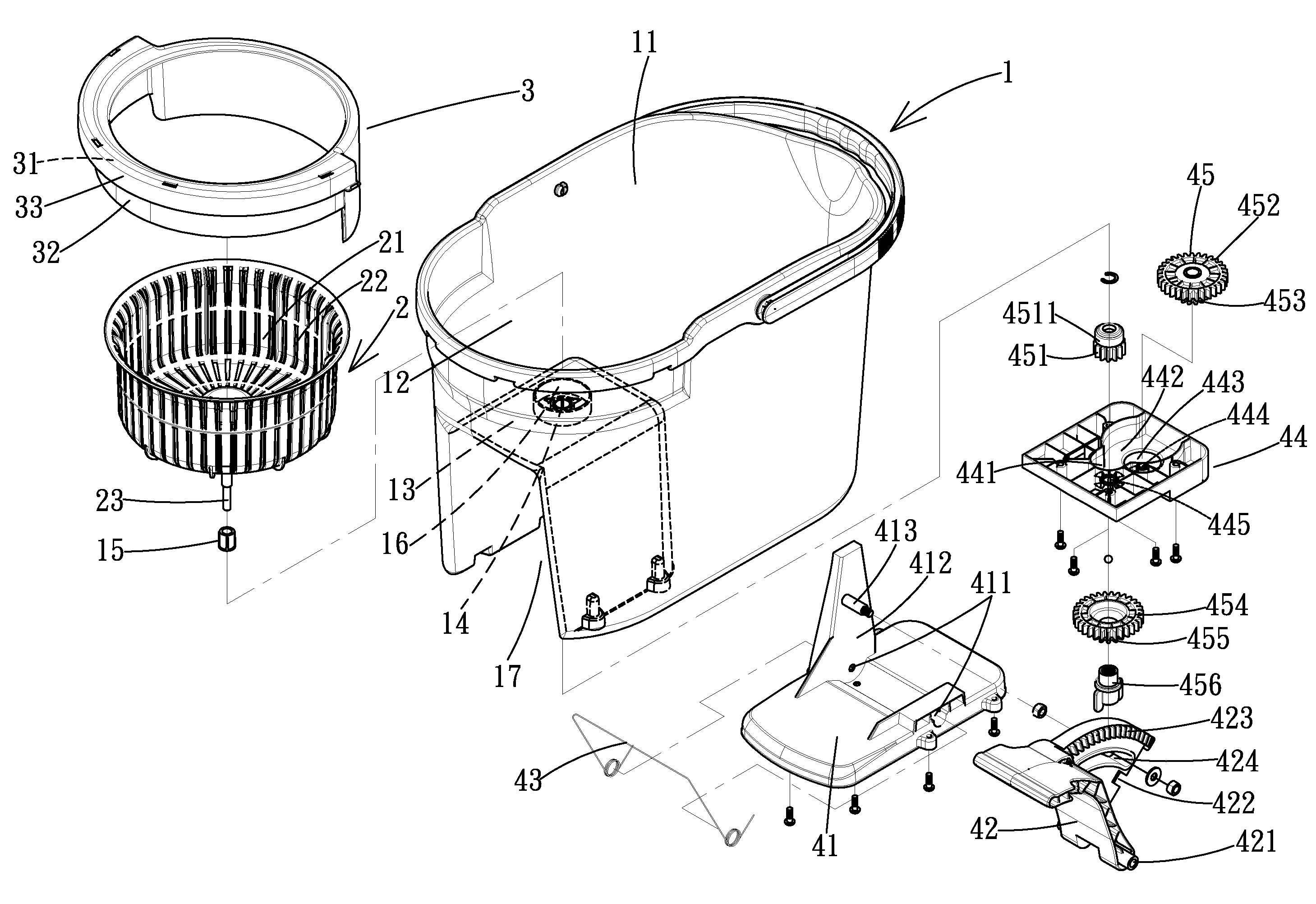
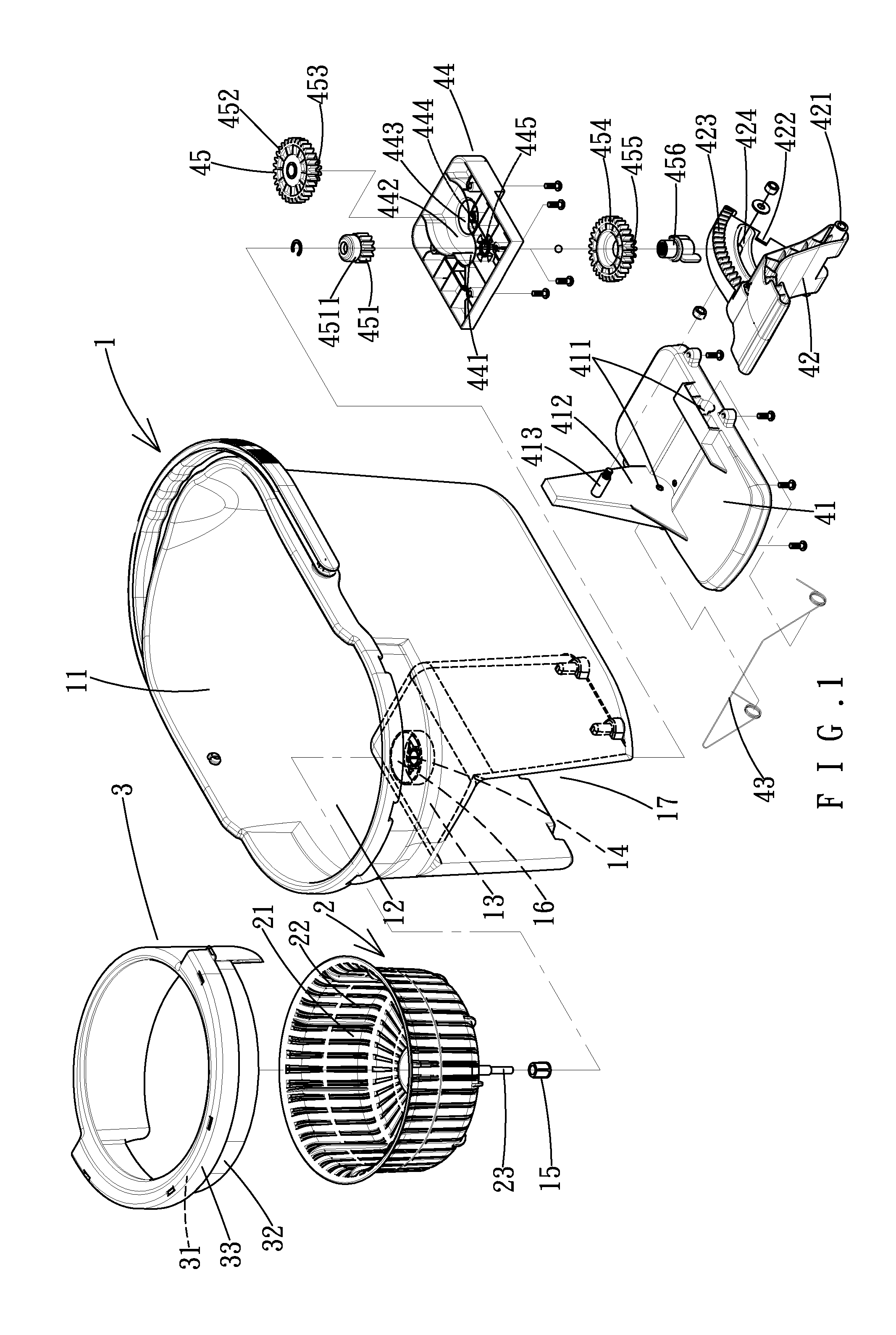
[0019]With reference to FIGS. 1-3, a centrifugal dehydrating device for a mop according to the preferred teachings of the present invention generally includes a bucket 1, a rotary container 2, a water fender 3, and a transmission mechanism 4. The bucket 1 includes a compartment 11 having a receiving space 12 in a side thereof. A mounting plate 13 is provided below the receiving space 12 and includes an axial hole 14 receiving an upper shaft sleeve 15 made of abrasion-resistant material. An annular fender 16 surrounds the axial hole 14. The bucket 1 further includes a recessed portion 17 below the mounting plate 13 and aligned with the receiving space 12.

[0020]The rotary container 2 is rotatably mounted in the receiving space 12 and includes a hollow cylinder 21 for receiving a bottom portion of a mop 5 (FIG. 4). The cylinder 21 includes a plurality of slits 22 through which water is passable. A shaft 23 is mounted to a bottom of the cylinder 21. An annular sleeve 24 is formed on the...


PUM

PropertyMeasurementUnit
angleaaaaaaaaaa
angleaaaaaaaaaa
angleaaaaaaaaaa

Abstract

A centrifugal dehydrating device includes a bucket receiving a cylinder for receiving a mop. A shaft is mounted to a bottom of the cylinder. An annular sleeve is formed on the bottom of the cylinder and engaged with an annular fender on a mounting plate. A water fender includes a skirt having a top portion with an annular groove for receiving a rim of the cylinder. An annular wing extends radially inward from the top portion of the skirt. Water splashing upward from the cylinder during rotation of the cylinder is stopped by the annular wing. A top seat is fixed to a bottom side of the mounting plate and receives a gear train. The gear train meshes with and is driven by a rack on a pedal such that stepping of the pedal causes rotation of the gear train, the shaft, and the cylinder.

Description

BACKGROUND OF THE INVENTION[0001]1. Field of the Invention[0002]The present invention relates to a dehydrating device for a mop and, more particularly, to a waterproof centrifugal dehydrating device for a mop with enhanced dehydrating efficiency and a longer service life.[0003]2. Description of the Related Art[0004]Conventionally, mops are manually wrung dry. To avoid time-consuming and laborsome wringing, centrifugal dehydrating devices have been proposed and generally include a bucket, a rotary container, and a transmission mechanism. The rotary container is mounted in the bucket and includes a one-way bearing. The transmission mechanism includes a pedal that can be stepped to move the rotary container in a single direction for dehydrating water contained in a mop placed in the rotary container. The water flying away from the mop under the action of the centrifugal force flows into the bucket. However, the transmission mechanism is liable to be splashed by the water flying away fr...

Claims


Application Information

Patent Timeline
Patent Type & Authority Patents(United States)
IPC IPC(8): A47L13/14B01D33/00B01D35/00B01D35/22B01D24/32D06F35/00D06F29/00F26B17/30C02F1/38A47L13/58F26B17/24
CPCA47L13/58
Inventor TSAI, YAO-FENG
Owner TSAI YAO FENG
Features
  • R&D
  • Intellectual Property
  • Life Sciences
  • Materials
  • Tech Scout
  • Unparalleled Data Quality
  • Higher Quality Content
  • 60% Fewer Hallucinations
Learn More