Check patentability & draft patents in minutes with Patsnap Eureka AI!

Magnetic head suspension and manufacturing method thereof with pair of piezoelectric adjusters

a manufacturing method and magnetic head suspension technology, applied in the direction of maintaining head carrier alignment, recording information storage, instruments, etc., can solve the problems of strain, poor vibration characteristics difficult so as to reduce the thickness and weight of the magnetic head suspension

Active Publication Date: 2013-02-05
SANCALL CORP
View PDF3 Cites 13 Cited by
  • Summary
  • Abstract
  • Description
  • Claims
  • Application Information

AI Technical Summary

Benefits of technology

[0022]In the magnetic head suspension according to the present invention, the flexure metal plate of the flexure part that is fixed to the load beam part and the supporting part includes a distal end side-center-support plate forming region and a proximal end side-center-support plate forming region that are positioned on distal and proximal sides within the open section of the supporting part, the paired right and left first and second-distal side-metal plates are fixed to the distal end section of the supporting part that is positioned on a distal side of the open section so as to be positioned on an outer side of the distal end side-center-support plate forming region in the suspension width direction, the paired right and left first and second-proximal side-metal plates are fixed to the proximal end section of the supporting part that is positioned on a proximal side of the open section so as to be positioned on an outer side of the proximal end side-center-support plate forming region in the suspension width direction, the first and second-distal side-metal plates form the first and second piezoelectric element-distal end side-support plates in cooperation with the distal end side-center-support plate forming region, and the first and second-proximal side-metal plates form the first and second piezoelectric element-proximal end side-support plates in cooperation with the proximal end side-center-support plate forming region. The thus configured magnetic head suspension makes it possible to form the distal end side-support plates and the proximal end side-support plates without three members being overlapped with and welded to one another, thereby reducing the thickness and the weight of the magnetic head suspension, and also effectively preventing the magnetic head suspension from being strained due to welding.

Problems solved by technology

Resultingly, there is posed a problem that it is difficult to reduce the thickness and weight of the magnetic head suspension.
Moreover, since the three members are welded to one another, weld strength must be heightened, which results in a problem that a strain is likely to occur in the magnetic head suspension.
The strain has a bad effect on floating posture of the magnetic head slider and vibration characteristics of the magnetic head suspension.

Method used


Image

  • Magnetic head suspension and manufacturing method thereof with pair of piezoelectric adjusters
  • Magnetic head suspension and manufacturing method thereof with pair of piezoelectric adjusters
  • Magnetic head suspension and manufacturing method thereof with pair of piezoelectric adjusters

Examples


first embodiment

[0064]Hereinafter, one preferred embodiment of a magnetic head suspension according to the present invention will be described, with reference to the attached drawings.

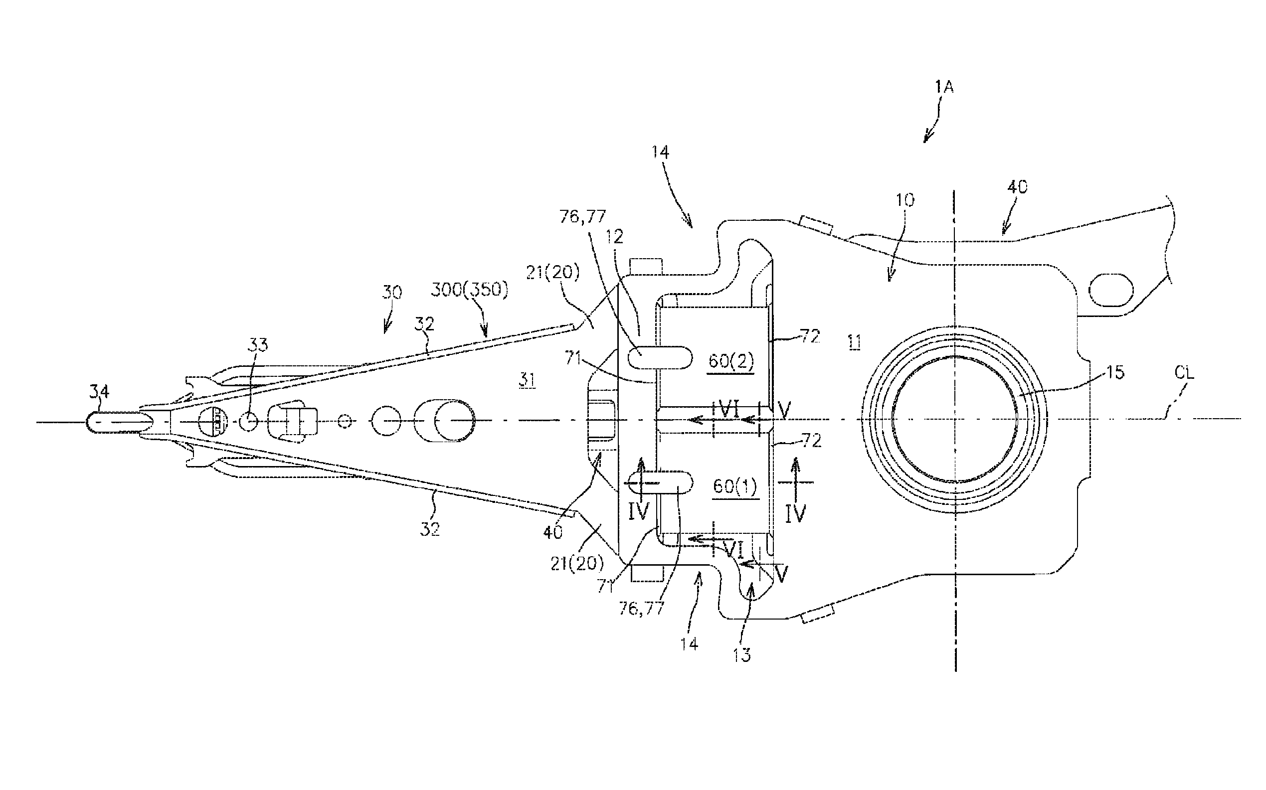
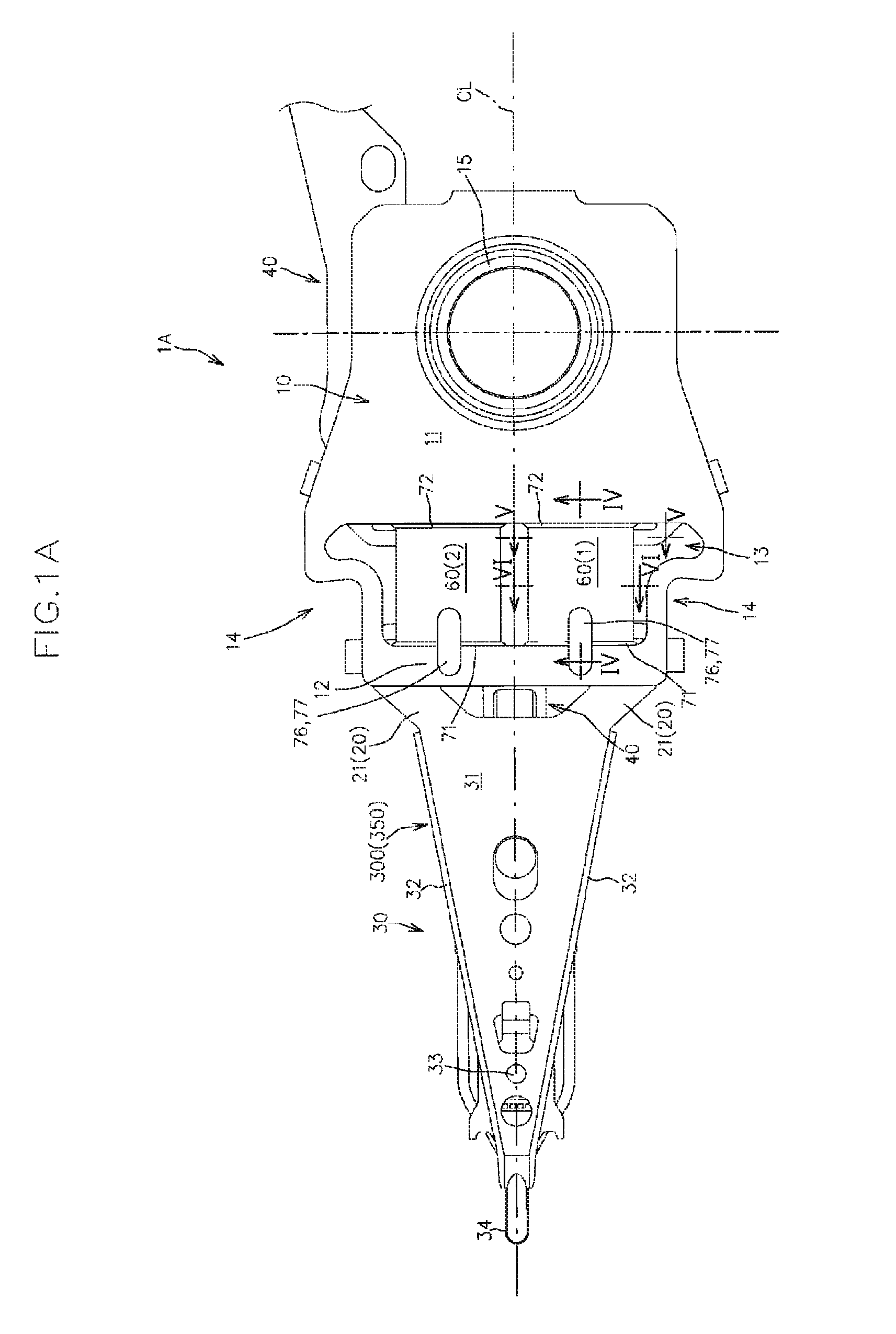
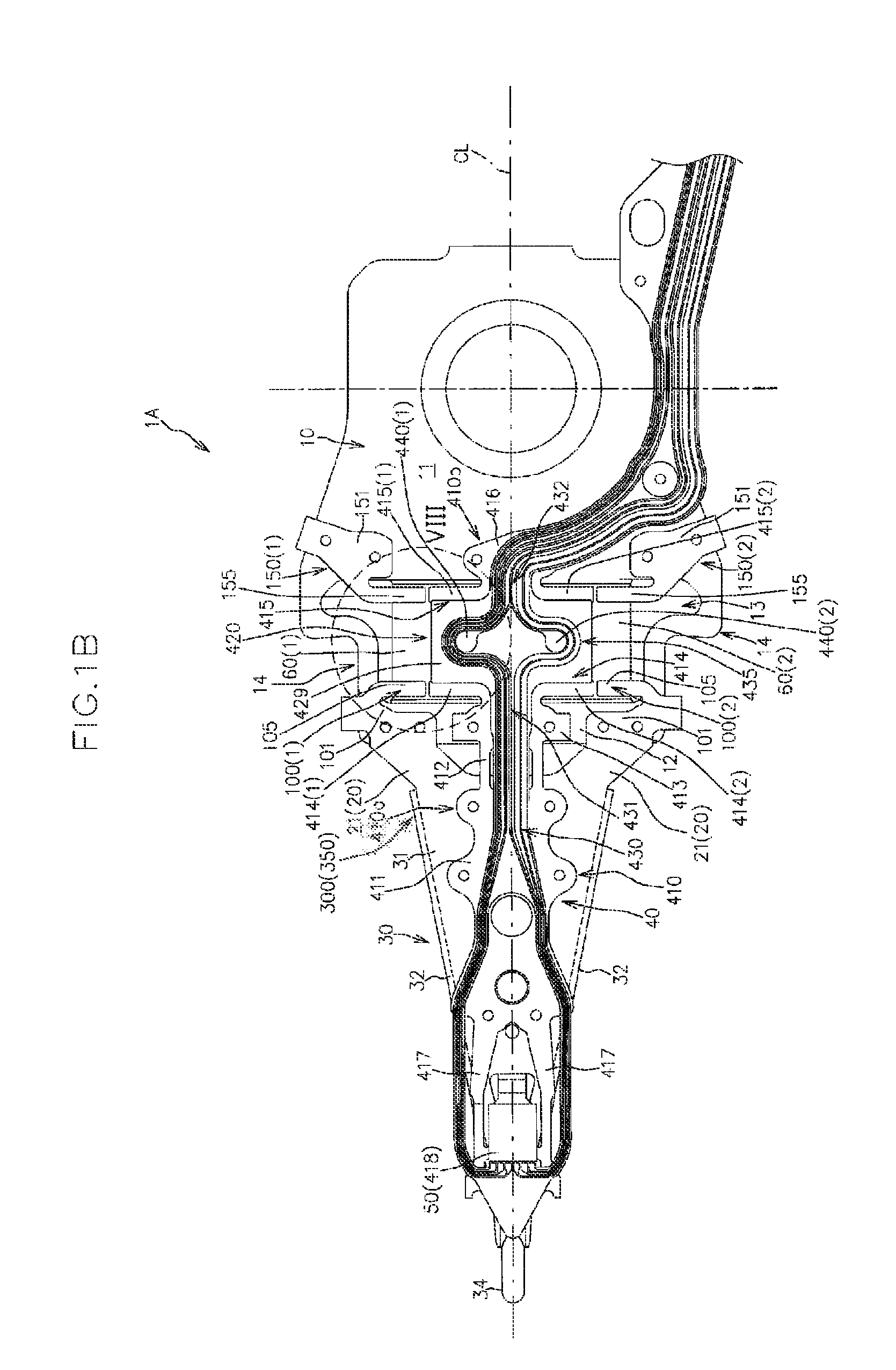
[0065]FIGS. 1A and 1B are a top view (a plan view as viewed from a side opposite from a disk surface), and a bottom view (a bottom plan view as viewed from a side close to the disk surface) of a magnetic head suspension 1A according to the present embodiment, respectively. FIG. 1B indicates welding points with using small circles.

[0066]As shown in FIGS. 1A and 1B, the magnetic head suspension 1A includes a load bending part 20 that generates a load for pressing a magnetic head slider 50 toward a disk surface, a load beam part 30 that transmits the load to the magnetic head slider 50, a supporting part 10 that supports the load beam part 30 via the load bending part 20 and is swung about a swing center directly or indirectly by a main actuator, a flexure part 40 that is supported by the load beam part 30 and the suppor...

second embodiment

[0197]Hereinafter, another embodiment of the magnetic head suspension according to the present invention will be described, with reference to the attached drawings.

[0198]FIG. 12 is a top view (a plan view as viewed from a side opposite from a disk surface) of a magnetic head suspension 2A according to the present embodiment.

[0199]In the figure, the members same as those in the first embodiment are denoted by the same reference numerals to omit the detailed description thereof.

[0200]Furthermore, for the purpose of easier understanding, the flexure part 40 is not shown, and the supporting part 10 and the first and second piezoelectric elements 60(1), 60(2) are shown with chain double-dashed line in FIG. 12.

[0201]As shown in FIG. 12, the magnetic head suspension 2A according to the present embodiment is different from the magnetic head suspension 1A according to the first embodiment in that it further includes a first connecting piece 110(1) that connects the first-distal side-metal pl...

third embodiment

[0209]Hereinafter, still another embodiment of the magnetic head suspension according to the present invention will be described, with reference to the attached drawings.

[0210]FIG. 13 is a top view (a plan view as viewed from a side opposite from a disk surface) of a magnetic head suspension 3A according to the present embodiment.

[0211]In the figure, the members same as those in the first and second embodiments are denoted by the same reference numerals to omit the detailed description thereof.

[0212]Furthermore, for the purpose of easier understanding, the flexure part 40 is not shown, and the supporting part 10 and the first and second piezoelectric elements 60(1), 60(2) are shown with chain double-dashed line in FIG. 13.

[0213]The magnetic head suspension 3A according to the present embodiment is different from the magnetic head suspensions 1A, 2A according to the first and second embodiments in that it further includes a first extending piece 120(1) that is positioned on an outer ...


PUM

PropertyMeasurementUnit
thicknessaaaaaaaaaa
thickaaaaaaaaaa
thicknessaaaaaaaaaa

Abstract

A flexure metal plate includes distal and proximal end side-center-support plate forming regions that are positioned on distal and proximal sides within an open section. To a distal end section of a supporting part that is positioned on a distal side of the open section, first and second-distal side-metal plates are fixed so as to be positioned on an outer side of the distal end side-center-support plate forming region in a width direction, and to a proximal end section of the supporting part that is positioned on a proximal side of the open section, first and second-proximal side-metal plates are fixed so as to be positioned on an outer side of the proximal end side-center-support plate forming region in the width direction. The first and second-distal side-metal plates form a distal end side-support plate in cooperation with the distal end side-center-support plate forming region.

Description

BACKGROUND OF THE INVENTION[0001]1. Field of the Invention[0002]The present invention relates to a magnetic head suspension for supporting a magnetic head slider that reads and / or writes data from and to a recording medium such as a hard disk drive, and also relates to a manufacturing method of the magnetic head suspension.[0003]2. Related Art[0004]Increase in capacity of a magnetic disk device requires improvement in accuracy for positioning a magnetic head slider on a target track. In this regard, there has been proposed a magnetic head suspension that enables coarse motion of a magnetic head slider in a seek direction by a main actuator such as a voice coil motor as well as micro motion of the magnetic head slider in the seek direction by a piezoelectric element functioning as a sub actuator.[0005]For example, Japanese Unexamined Patent Application Publication No. 2002-050140 (hereinafter referred to as prior art document) proposes to provide a magnetic head suspension with the p...

Claims


Application Information

Patent Timeline
Patent Type & Authority Patents(United States)
IPC IPC(8): G11B5/56G11B21/24G11B5/60G11B21/10G11B21/21
CPCG11B5/4873Y10T29/42Y10T29/49037Y10T29/49021
Inventor FUJIMOTO, YASUOTAKASUGI, SATORUMASHIMO, KENJI
Owner SANCALL CORP
Features
  • R&D
  • Intellectual Property
  • Life Sciences
  • Materials
  • Tech Scout
  • Unparalleled Data Quality
  • Higher Quality Content
  • 60% Fewer Hallucinations
Learn More