Vehicle burglar alarm circuit
a technology for burglar alarms and circuits, applied in the direction of emergency protective arrangements for automatic disconnection, digital computer details, etc., can solve the problems of increasing the number of parts and the cost, and achieve the effect of satisfactory sound pressure level and simple circuit configuration
- Summary
- Abstract
- Description
- Claims
- Application Information
AI Technical Summary
Benefits of technology
Problems solved by technology
Method used
Image

Examples
first embodiment
[0029](First Embodiment)
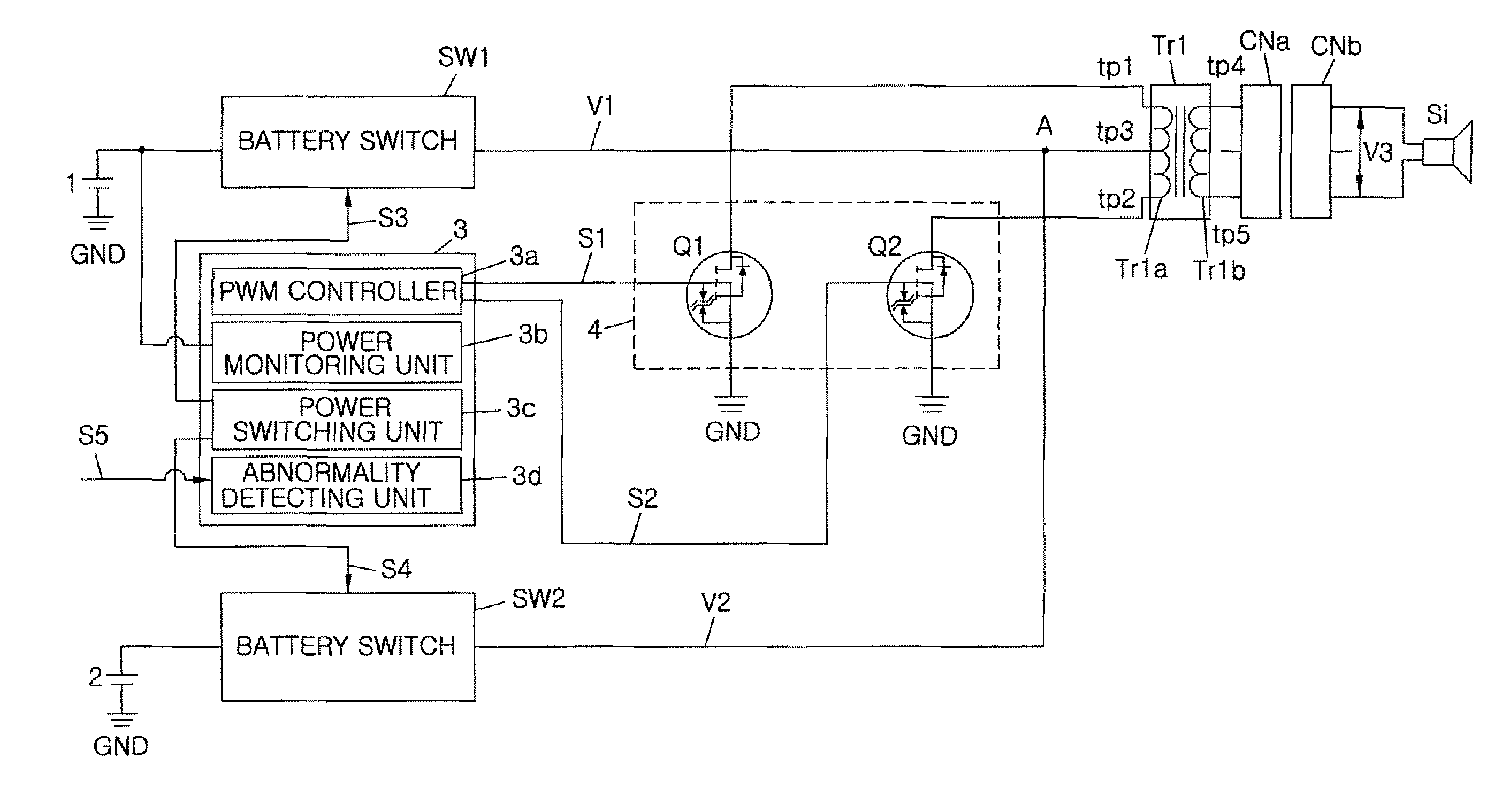
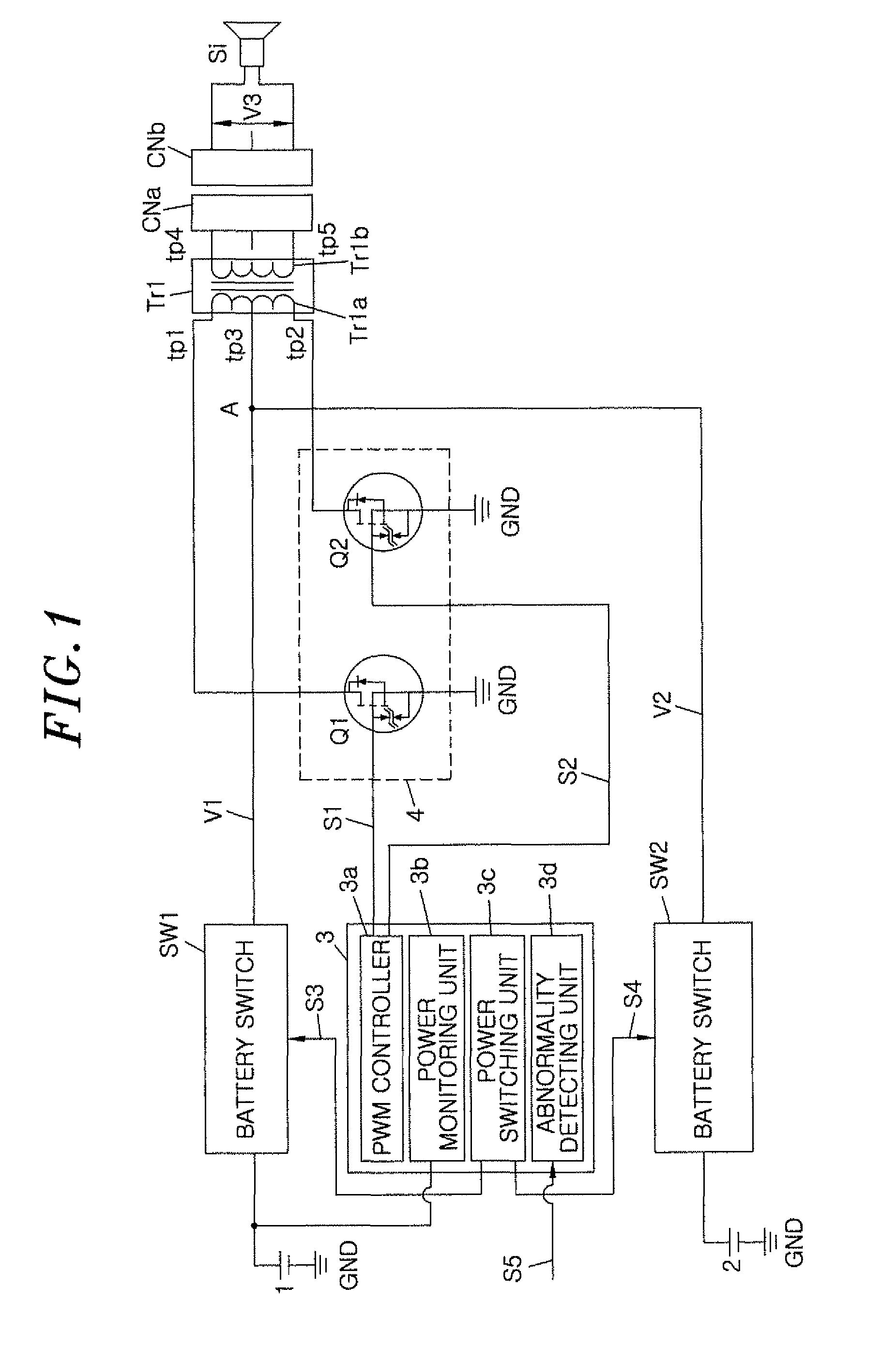
[0030]In accordance with a first embodiment of the present invention, a vehicle burglar alarm circuit includes a main battery 1 configured to be detachable and attachable, an internal battery 2, a control unit 3, a sounding body driving unit 4, a transformer Tr1 and a siren (sounding body) Si.
[0031]The Transformer Tr1 includes a primary coil Tr1a (input unit) and a secondary coil Tr1b (output unit). A first and a second tap tp1 and tp2 are respectively connected to opposite ends of the primary coil Tr1a, and a center tap tp3 is connected to the center of primary coil Tr1a, the center tap tp3 being positioned between the taps tp1 and tp2. The first tap tp1 and the second tap tp2 are respectively connected to switching elements Q1 and Q2, and the center tap tp3 is connected to the main battery 1 and the internal battery 2.
[0032]The secondary coil Tr1b is magnetically connected to the primary coil Tp1a, and output taps tp4 and tp5 are respectively connected to o...
second embodiment
[0057](Second Embodiment)
[0058]A vehicle burglar alarm circuit including an autotransformer to drive the siren Si in accordance with a second embodiment of the present invention will be described. In the second embodiment, components having substantially the same function as those of the first embodiment are denoted by the same reference characters. FIG. 5 a schematic circuit configuration view showing the vehicle burglar alarm circuit including an autotransformer.
[0059]A transformer Tr2 includes an autotransformer, one coil of which has taps 11 to 15. A center tap tp13 is connected to the center of the coil, and output taps tp14 and tp15 are respectively connected to opposite ends of the coil. A first tap tp11 and a second tap tp12 are respectively connected to the coil at locations between taps tp13 and tp14, and between taps tp13 and tp15, respectively.
[0060]The first tap tp11 is connected to the drain of the switching element Q1, and the second tap tp12 is connected to the drain...
PUM
 Abstract
Description
Claims
Application Information
 - R&D
- Intellectual Property
- Life Sciences
- Materials
- Tech Scout
- Unparalleled Data Quality
- Higher Quality Content
- 60% Fewer Hallucinations
Browse by: Latest US Patents, China's latest patents, Technical Efficacy Thesaurus, Application Domain, Technology Topic, Popular Technical Reports.
© 2025 PatSnap. All rights reserved.Legal|Privacy policy|Modern Slavery Act Transparency Statement|Sitemap|About US| Contact US: help@patsnap.com