Check patentability & draft patents in minutes with Patsnap Eureka AI!

Electronic equipment control system

a control system and electronic equipment technology, applied in the field of electronic equipment control system, can solve the problem that the other electric equipment cannot set the broadcast content setting information of the other electric equipment, and achieve the effect of reducing the number of devices

Inactive Publication Date: 2013-03-26
FUNAI ELECTRIC CO LTD
View PDF14 Cites 2 Cited by
  • Summary
  • Abstract
  • Description
  • Claims
  • Application Information

AI Technical Summary

Benefits of technology

The present invention provides an electronic equipment control system that simplifies the setting of broadcast content setting information for each piece of electric equipment connected to a network. The system allows for easy sharing of broadcast content setting information among multiple pieces of equipment. The specific electric equipment, such as a portable terminal, can set and input the broadcast content setting information for other pieces of equipment connected to the network. This improves the usability of the user and makes the setting of the broadcast content easier for each piece of equipment. The system also allows for easy updating of the broadcast content setting information based on the view history of other pieces of equipment. Overall, the invention provides a more efficient and user-friendly electronic equipment control system.

Problems solved by technology

However, by the techniques disclosed in these prior art documents, certain electric equipment can utilize the broadcast content view history in other electric equipment in a system including a plurality of pieces of electric equipment connected to one another, or electric equipment can set broadcast content setting information such as view limitation information therein, but by the techniques, the electronic equipment cannot set the broadcast content setting information of the other electric equipment therein.

Method used


Image

  • Electronic equipment control system
  • Electronic equipment control system
  • Electronic equipment control system

Examples


first embodiment

[0058]First, an electronic equipment control system Sa of a first embodiment to which the present invention is applied will be described with reference to FIGS. 1-6.

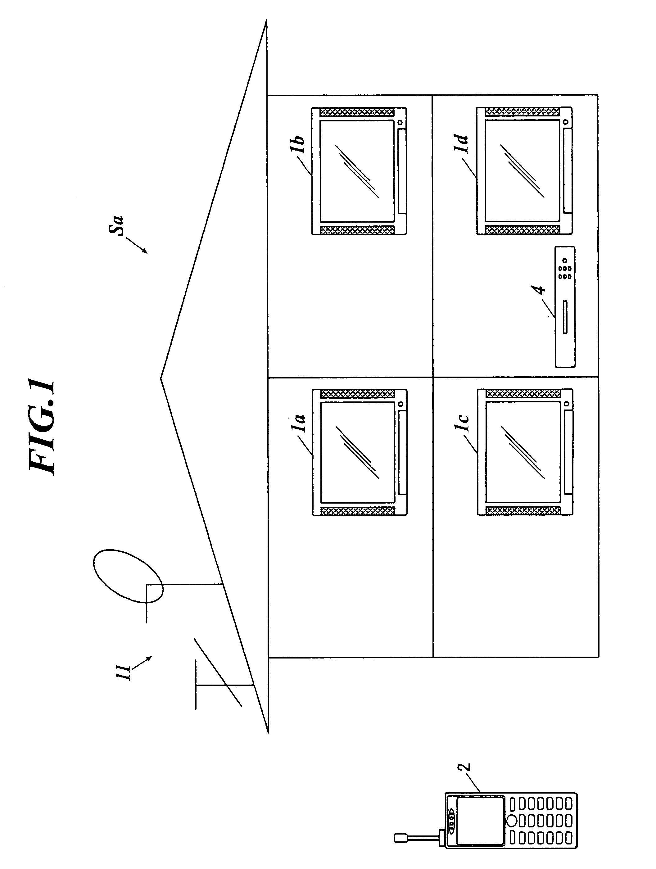
[0059]In the electronic equipment control system Sa of the present first embodiment, a plurality of pieces of electric equipment is connected with one another through a network N1. The following description is given on the supposition that a piece of specific electric equipment among these pieces of electric equipment is, for example, a portable telephone (portable terminal) 2, and that the other pieces of electric equipment other than the specific electric equipment are television receivers 1 (for example, television receivers 1a, 1b, 1c and 1d). These television receivers 1 may have the configuration including a connected piece of external equipment 4 such as a hard disc drive (HDD) recorder and a set top box (STB) like, for example, the television receiver 1d.

[0060]The network N1, to which the specific electric equip...

second embodiment

[0127]Next, an electronic equipment control system Sb of a second embodiment to which the present invention is applied will be described with reference to FIGS. 7-10.

[0128]In the electronic equipment control system Sb of the present first embodiment, a plurality of pieces of electric equipment is connected with one another through a network N2. The following description is given on the supposition that the pieces of electric equipment are television receivers 3 (for example, television receivers 3a, 3b, 3c and 3d).

[0129]First, the configurations of the television receivers 3a, 3b, 3c and 3d connected to the network N2 are described with reference to FIG. 7.

[0130]Incidentally, the configurations of the television receivers 3a, 3b, 3c and 3d are supposed to be a common one, and one television receiver 3a is especially adopted here to be described and the descriptions of the other television receivers 3b, 3c and 3d are omitted.

[0131]The television receiver 3a is configured to include, ...


PUM


Abstract

An electronic equipment control system including a plurality of pieces of electric equipments connected with one another through a network. A piece of electric equipment among the plurality of pieces of electric equipments comprises: a setting and inputting unit to set and input broadcast content setting information regarding view of a broadcast content; a broadcast content setting information storage unit to store the content setting information; a transmission unit to transmit the content setting information set and input by the setting and inputting unit to another piece of electric equipment connected to the network; a reception unit to receive the content setting information transmitted from another piece of electric equipment connected to the network; and an update unit to update the content setting information stored in the content setting information storage unit based on the content setting information received by the reception unit.

Description

BACKGROUND OF THE INVENTION[0001]1. Field of the Invention[0002]The present invention relates to an electronic equipment control system including a plurality of pieces of electric equipment through a network.[0003]2. Related Art[0004]Various techniques for effectively utilizing broadcast content setting information such as broadcast content view history and broadcast content view limitation information have conventionally been proposed in connection with electric equipment such as a television receiver.[0005]For example, JP-A 2005-295357 discloses a broadcast reception apparatus in which a certain broadcast reception apparatus can utilize the view history information stored in another broadcast reception apparatus. In the broadcast reception apparatus, a portable broadcast reception apparatus stores the view history information of broadcast contents into the memory thereof, and reads the view history information from the memory to transmit the read view history information with an i...

Claims


Application Information

Patent Timeline
Patent Type & Authority Patents(United States)
IPC IPC(8): H04N7/16H04N5/44H04N7/173H04N21/475H04N21/61
CPCH04H60/33H04N7/163H04N21/43615H04N21/44222H04N21/47H04H60/47H04H60/65H04H60/92H04H2201/80
Inventor KAWAI, MASANORI
Owner FUNAI ELECTRIC CO LTD
Features
  • R&D
  • Intellectual Property
  • Life Sciences
  • Materials
  • Tech Scout
  • Unparalleled Data Quality
  • Higher Quality Content
  • 60% Fewer Hallucinations
Learn More