Supercharge Your Innovation With Domain-Expert AI Agents!

Recording apparatus

a recording apparatus and vibration damping technology, applied in the field of recording apparatuses, can solve the problems of inability to effectively dampen vibration in a direction parallel to the recording surface, inability to effectively prevent degradation of recording quality, etc., and achieve the effect of effectively dampening vibration and effectively preventing degradation of recording quality

Active Publication Date: 2013-04-23
BROTHER KOGYO KK
View PDF7 Cites 0 Cited by
  • Summary
  • Abstract
  • Description
  • Claims
  • Application Information

AI Technical Summary

Benefits of technology

[0006]According to the above technique, an effect of dampening vibration in a direction perpendicular to a recording surface of the recording head is expectable, however, it is difficult to effectively dampen vibration in a direction parallel to the recording surface. That is, the above technique is not able to effectively prevent degradation in recording quality caused by the vibration in this direction.
[0007]An object of the present invention is to provide a recording apparatus which effectively dampens vibration not only in the direction perpendicular to the recording surface but also in the direction(s) parallel to the recording surface and is excellent in preventing degradation in recording quality.

Problems solved by technology

According to the above technique, an effect of dampening vibration in a direction perpendicular to a recording surface of the recording head is expectable, however, it is difficult to effectively dampen vibration in a direction parallel to the recording surface.
That is, the above technique is not able to effectively prevent degradation in recording quality caused by the vibration in this direction.

Method used


Image

  • Recording apparatus
  • Recording apparatus
  • Recording apparatus

Examples


first embodiment

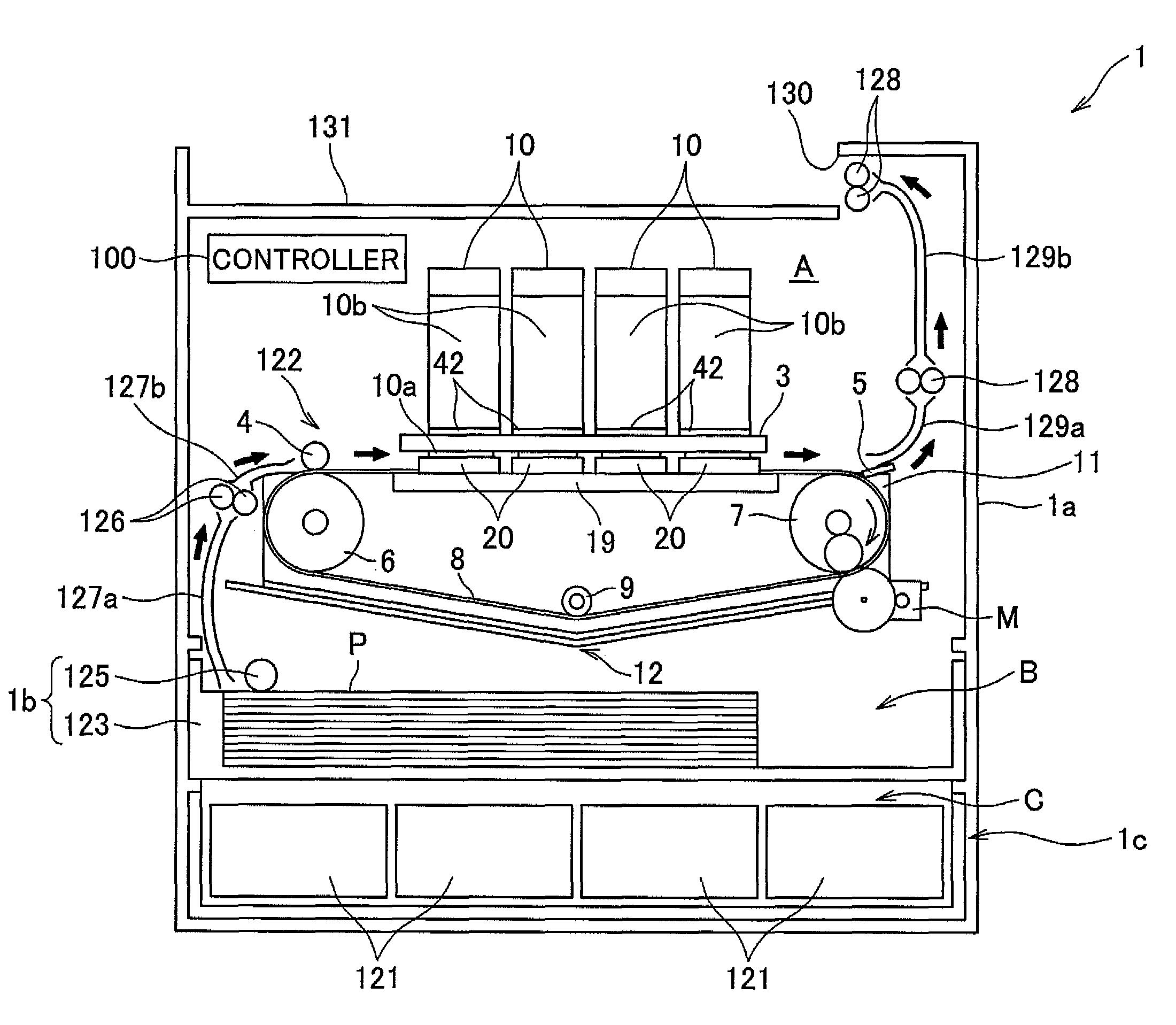
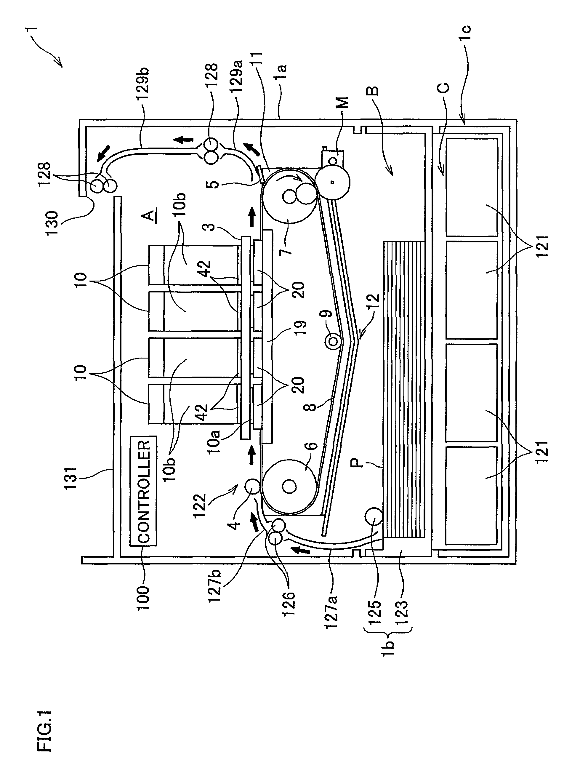
[0022]First, referring to FIG. 1, description will be given on general structure of an ink jet printer 1 of the present invention.

[0023]As shown in FIG. 1, the printer 1 has a housing 1a of a rectangular parallelepiped shape. On the top panel of the housing 1a, a discharged paper receiver 131 is formed, which receives a sheet P having received recording thereon and discharged from an opening 130. The internal space of the housing 1a is divided into spaces A, B, and C, from the top to the bottom. The space A contains: four ink jet heads 10 which respectively eject different colors of ink of magenta, cyan, yellow, and black; a conveyor unit 122 which conveys a sheet P (a printing medium); and a controller 100 which controls operation of each component of the printer 1. The heads 10 are disposed so that the longitudinal direction of each head 10 is parallel to a main scanning direction. The conveyor unit 122 conveys a sheet P in a sub scanning direction. In the spaces B and C, a paper ...


PUM


Abstract

A recording apparatus includes: a recording head which conducts recording onto a printing medium; a supporter which supports the recording head at a recording position; and a vibration damper interposed between the recording head and the supporter. The recording head includes a recording surface facing a printing medium and a gradient inclined relative to the recording surface. The gradient is provided at an end of the recording surface. The vibration damper abuts: at least one of the recording surface and a surface parallel to the recording surface of the recording head; and the gradient.

Description

CROSS REFERENCE TO RELATED APPLICATION[0001]This application claims priority from Japanese Patent Application No. 2009-049234, which was filed on Mar. 3, 2009, the disclosure of which is herein incorporated by reference in its entirety.BACKGROUND OF THE INVENTION[0002]1. Field of the Invention[0003]The present invention relates to a recording apparatus which records an image onto a printing medium.[0004]2. Description of Related Art[0005]In an ink-jet recording apparatus, for example, vibration caused at the time of driving a recording head may degrade recording quality. In order to alleviate this problem, there has been a known technique of providing a vibration absorber between the recording head and a holder which holds the recording head.SUMMARY OF THE INVENTION[0006]According to the above technique, an effect of dampening vibration in a direction perpendicular to a recording surface of the recording head is expectable, however, it is difficult to effectively dampen vibration in...

Claims


Application Information

Patent Timeline
Patent Type & Authority Patents(United States)
IPC IPC(8): B41J2/165
CPCB41J2/155B41J11/06B41J19/04
Inventor KATO, HIDEAKI
Owner BROTHER KOGYO KK
Features
  • R&D
  • Intellectual Property
  • Life Sciences
  • Materials
  • Tech Scout
  • Unparalleled Data Quality
  • Higher Quality Content
  • 60% Fewer Hallucinations
Learn More