Supercharge Your Innovation With Domain-Expert AI Agents!

Auto-measurement and calibration of DC resistance in current sensing applications

a current sensing and dc technology, applied in the direction of instruments, code conversion, transmission systems, etc., can solve the problems of affecting the reliability of processors in the computer system, improper voltage provided by the power supply, and errors introduced into the current sensing process, and achieve the effect of effective resistance in memory

Active Publication Date: 2013-05-28
GOOGLE LLC
View PDF17 Cites 4 Cited by
  • Summary
  • Abstract
  • Description
  • Claims
  • Application Information

AI Technical Summary

Benefits of technology

This approach enhances the accuracy of current sensing by accounting for parasitic resistances and temperature variations, ensuring reliable power supply and efficient operation of power conversion systems by storing calibrated voltage and resistance values for future use.

Problems solved by technology

Each of these factors may introduce errors into the current sensing process.
This may lead to improper voltage provided by the power supply, which in turn may affect the reliability of processors in the computer system.
Merely measuring sample circuit boards during manufacture may not provide an adequate baseline DCR for all circuit boards being produced.

Method used


Image

  • Auto-measurement and calibration of DC resistance in current sensing applications
  • Auto-measurement and calibration of DC resistance in current sensing applications
  • Auto-measurement and calibration of DC resistance in current sensing applications

Examples


Embodiment Construction

[0038]The aspects, features and advantages of the present invention will be appreciated when considered with reference to the following description of preferred embodiments and accompanying figures. The same reference numbers in different drawings may identify the same or similar elements. Furthermore, the following description does not limit the present invention; rather, the scope of the invention is defined by the appended claims and equivalents.

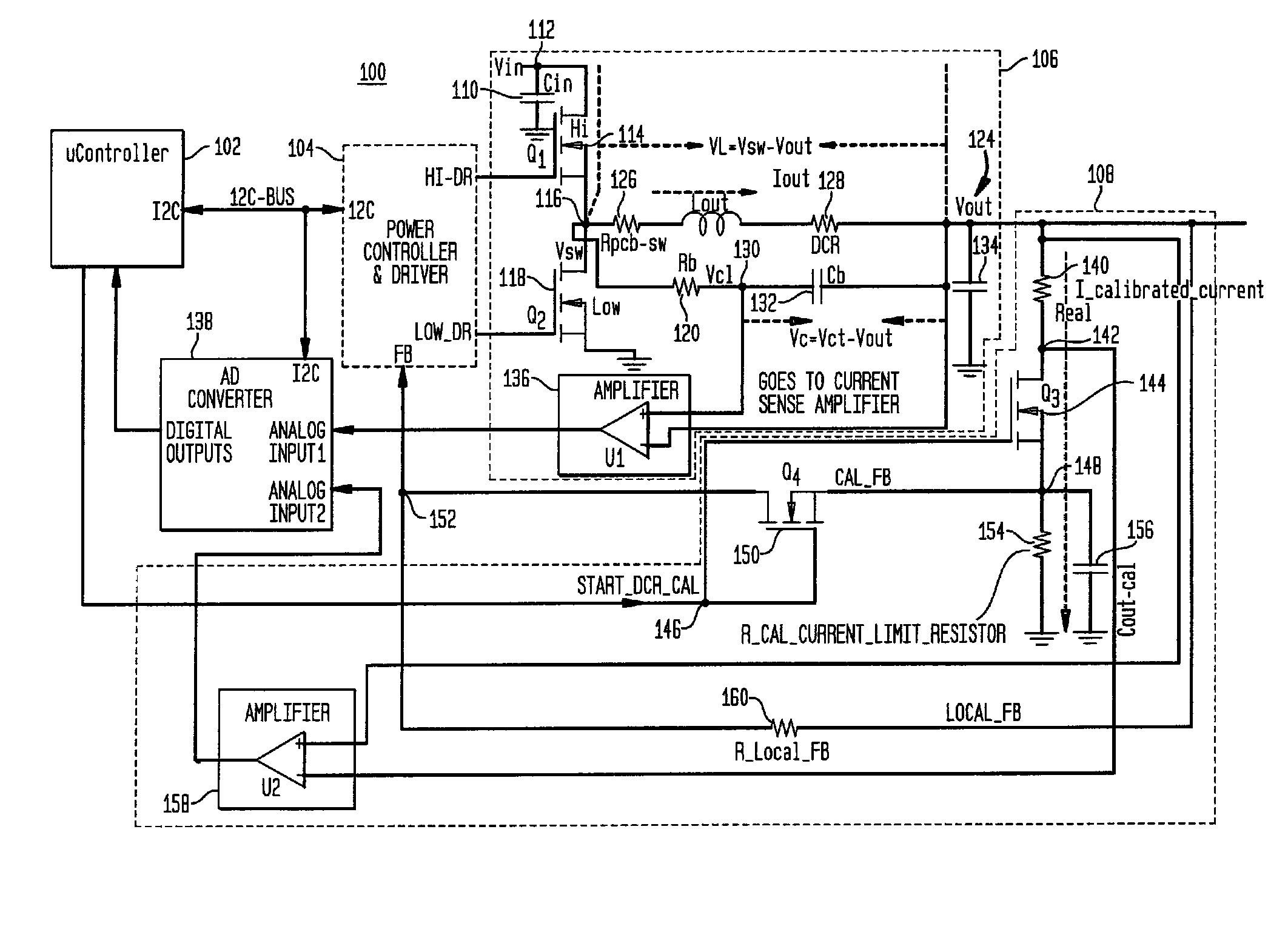
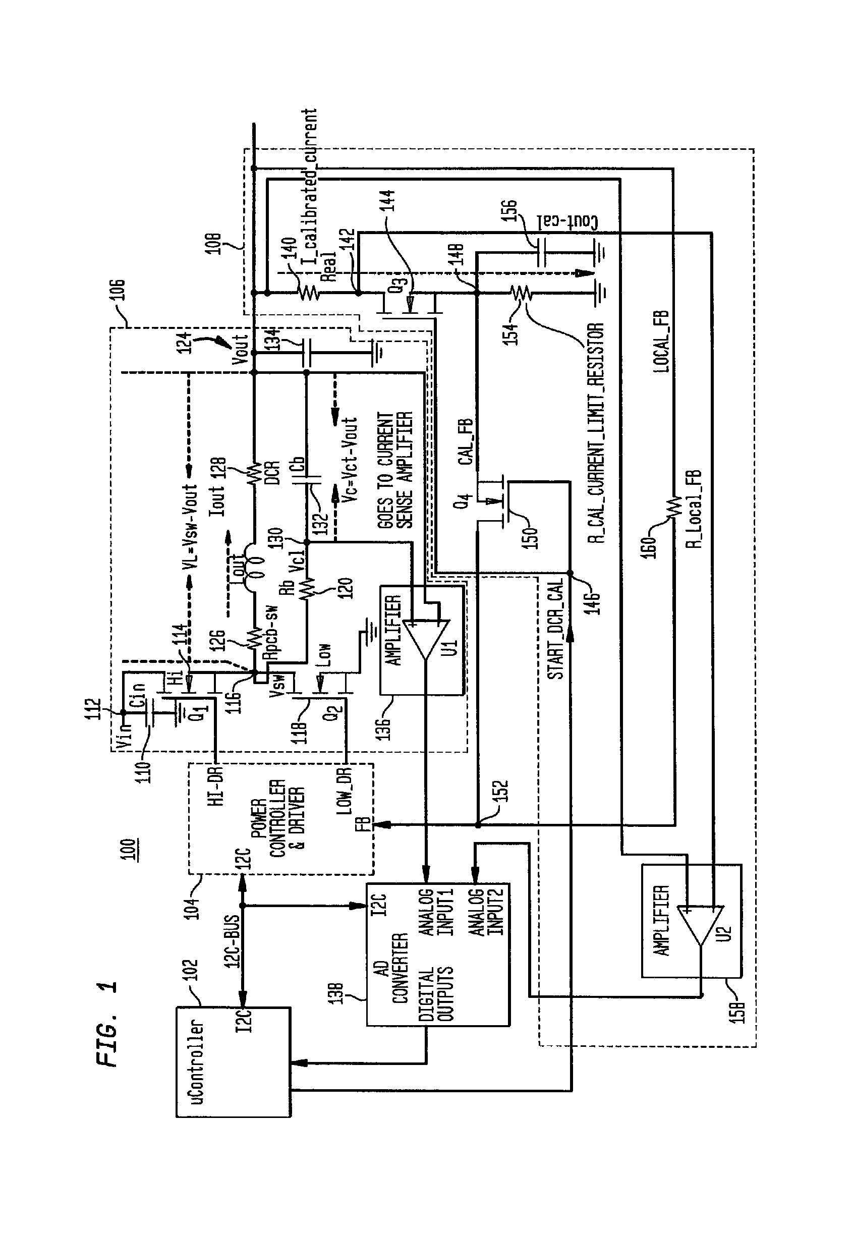
[0039]FIG. 1 provides an embodiment of a current sensing measurement and calibration architecture 100. As shown, the architecture 100 may include a system controller such as microcontroller 102, a power controller / driver 104, a buck converter circuit 106 and a measurement and calibration circuit 108. For ease of illustration, certain lines in the architecture 100 are shown as crossing. However, only intersecting lines attached by a node indicator (e.g., illustrated as a rectangular intersection point) are electrically coupled to one anoth...


PUM


Abstract

The present invention pertains to calibration in current sensing applications. Power conversion systems such as those used in computer architectures may employ step down converters such as buck converters or other types of converters. The present invention provides calibration processes and devices to account for various parasitic resistances which are found in such systems. A calibration circuit may be coupled to the buck converter or other power conversion to determine a calibrated voltage signal for the output of the power converter. An effective DC resistance may be determined and programmed for use by a control device used. In this way, the parasitic resistances are taken into account to obtain an accurate estimate of the actual current. In turn, this enables power converters and other devices to operate within specification requirements.

Description

CROSS REFERENCE TO RELATED APPLICATIONS[0001]This application is a continuation of U.S. application Ser. No. 12 / 786,706, filed on May 25, 2010, which is a continuation of U.S. application Ser. No. 12 / 315,655, filed on Dec. 5, 2008 and issued on Jun. 22, 2010 as U.S. Pat. No. 7,741,983, the entire disclosures of which are incorporated herein by reference.BACKGROUND OF THE INVENTION[0002]1. Field of the Invention[0003]The present invention relates generally to measurement and calibration of resistance in current sensing applications, and is particularly suited to measurement and calibration of inductor resistance, PCB resistance and relates parasitic resistances.[0004]2. Description of Related Art[0005]Power conversion is an important process which occurs in a variety of systems for many different applications. One such application is in a power converter for a computing system. In a power converter application, a buck converter may be used to provide a stepped-down DC voltage to vari...

Claims


Application Information

Patent Timeline
Patent Type & Authority Patents(United States)
IPC IPC(8): H03M1/10
CPCG01R19/0092G01R35/007G01R35/005
Inventor LAKSHMIKANTHAN, SRIKANTHLIPIANSKY, EDUARDO M.AMMU, UDAYA KIRAN
Owner GOOGLE LLC
Features
  • R&D
  • Intellectual Property
  • Life Sciences
  • Materials
  • Tech Scout
  • Unparalleled Data Quality
  • Higher Quality Content
  • 60% Fewer Hallucinations
Learn More