Supercharge Your Innovation With Domain-Expert AI Agents!

Direct contact heat exchanger and methods for making and using same

a heat exchanger and direct contact technology, applied in the field of direct contact heat exchangers and methods for making and using same, can solve the problems of low heat transfer coefficient from the vapor to the intercooler tubes, large and expensive high pressure heat exchangers, and negative impact on the economics of the entire system

Active Publication Date: 2013-06-11
KALINA POWER LTD
View PDF5 Cites 0 Cited by
  • Summary
  • Abstract
  • Description
  • Claims
  • Application Information

AI Technical Summary

Benefits of technology

The system achieves high thermal efficiency and cost-effectiveness by converting a portion of the heat into electrical power and usable heat, reducing fuel consumption by 20-25% compared to conventional Rankine cycle systems, while maintaining a high power output and thermal efficiency.

Problems solved by technology

Moreover, the intercooled stream in the prior art is in the form of a vapor, and therefore the heat transfer coefficient from the vapor to the intercooler tubes is low.
As a result, such an intercooler must be a very large and very expensive high pressure heat exchanger.
This in turn has a very negative impact on the economics of the entire system.

Method used


Image

  • Direct contact heat exchanger and methods for making and using same
  • Direct contact heat exchanger and methods for making and using same
  • Direct contact heat exchanger and methods for making and using same

Examples


embodiment

FIG. 1A Embodiment

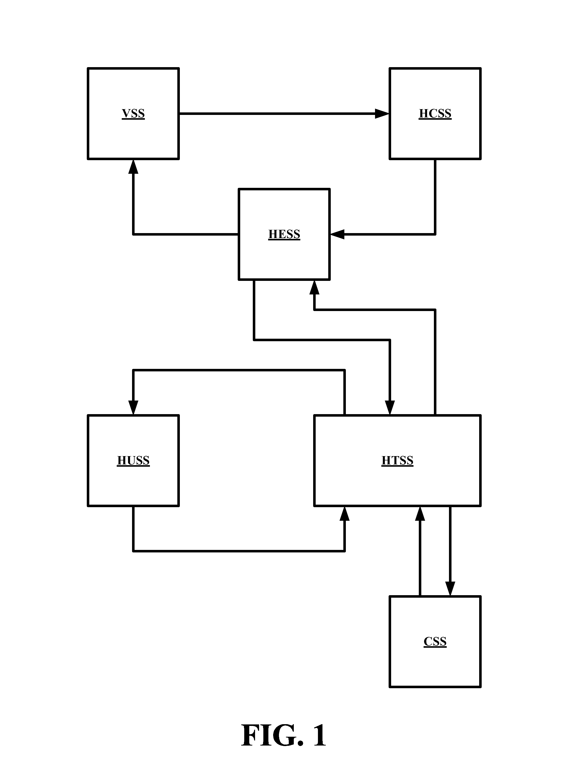
[0068]Referring now to FIG. 1, a conceptual flow diagram an embodiment of a system of this invention, generally CS-27, is shown to include a heat conversion subsystem HCSS, a vaporization subsystem VSS, a heat exchange and separation subsystem HESS, a heat transfer and separation subsystem HTSS, a heat utilization subsystem HUSS and a condensation subsystem CSS. The HUSS can be any subsystem that can utilized waste heat such as a factory, an refinery, an office building for heating, heating for homes, cities, towns, subdivisions or any other subsystem that can utilize a ready heat source of a low to moderate temperature.

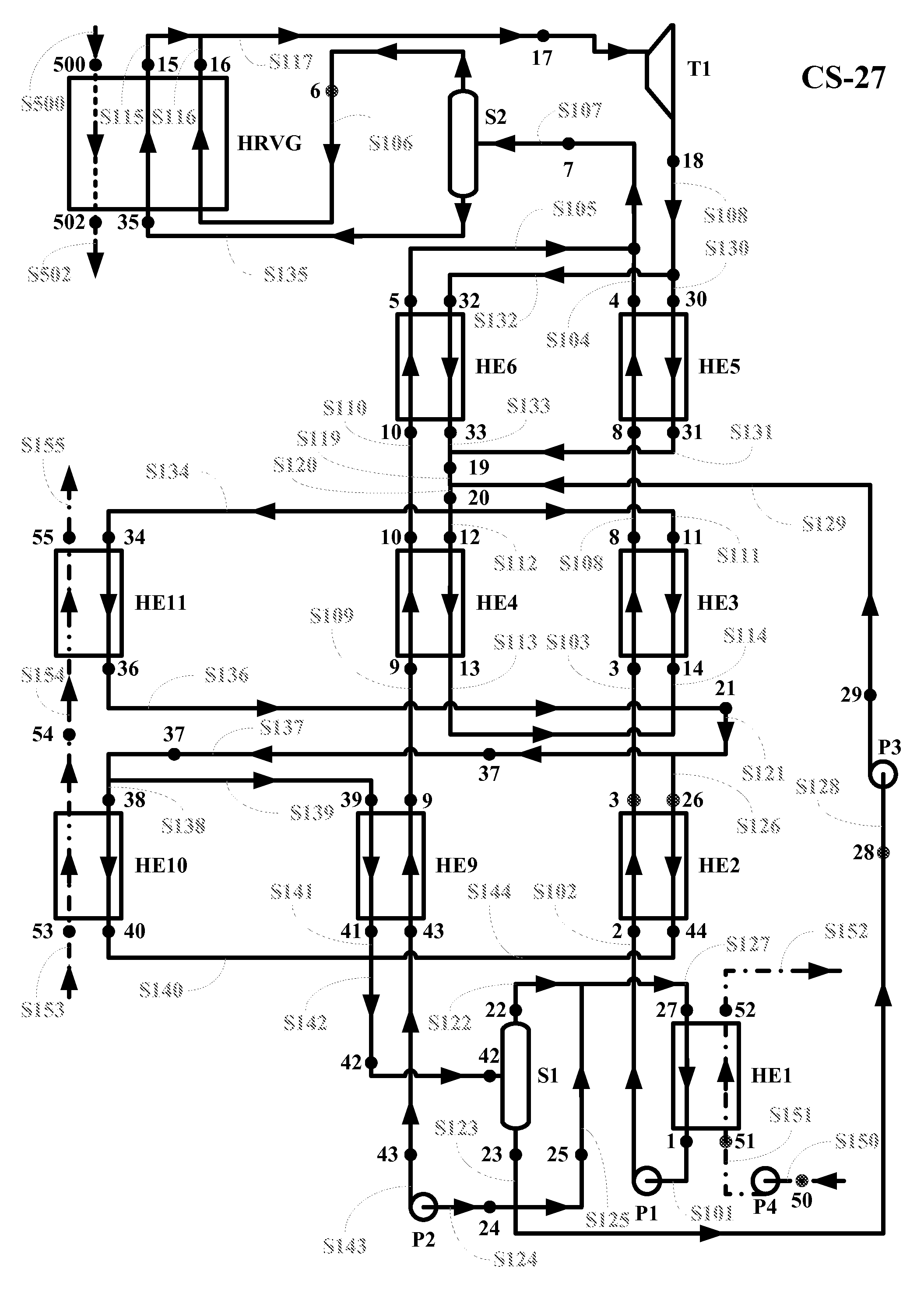
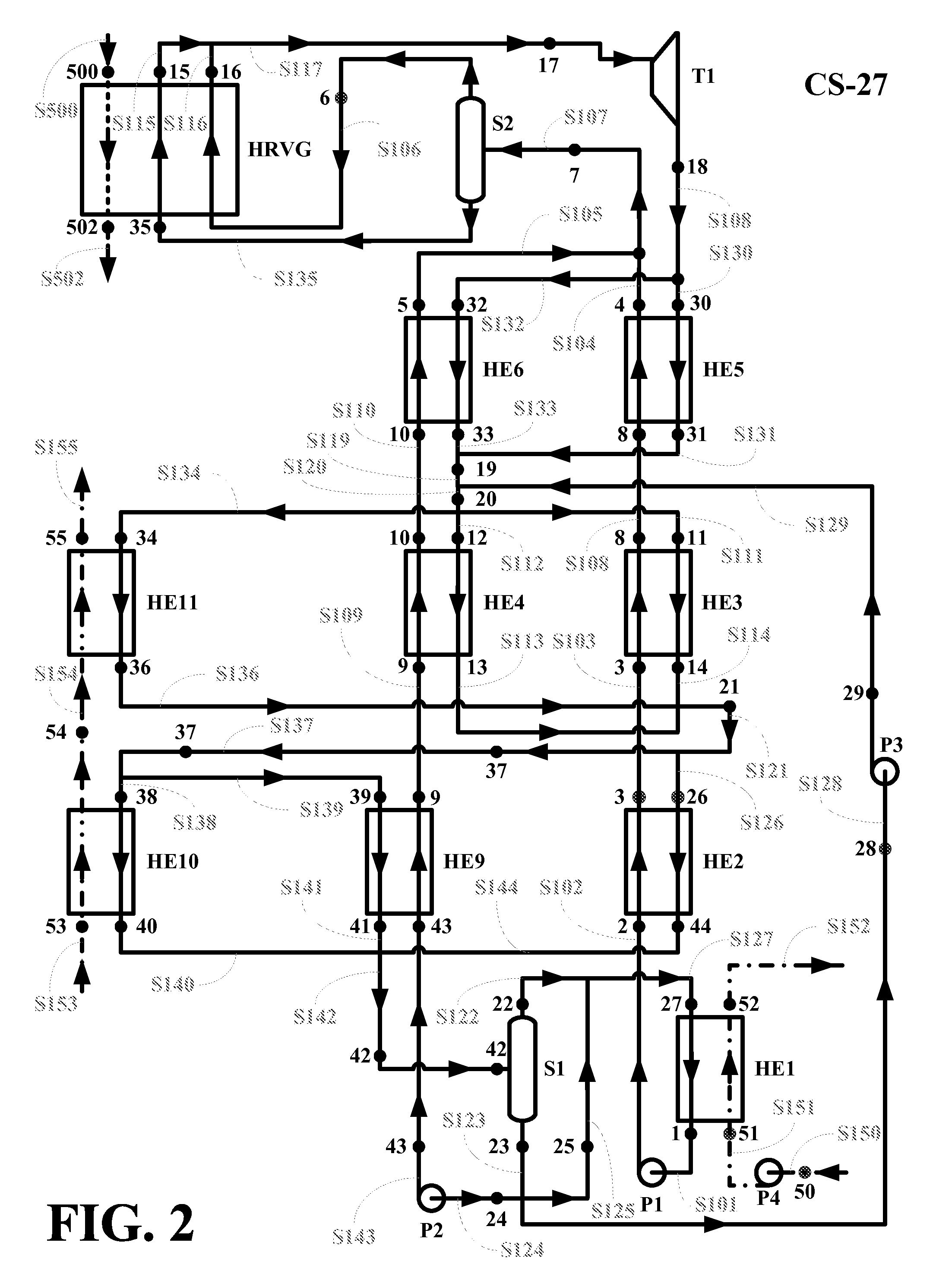
[0069]Referring now to FIG. 2, a conceptual flow diagram an embodiment of a system of this invention, generally CS-27, is shown to include a fully condensed, multi-component rich solution stream S101 having parameters as at a point 1 enters into a feed pump P1, where it is pumped to a specified higher pressure forming a pressurized fully condensed, ...


PUM


Abstract

A system and method are disclosed for the combined production of power and heat from an external heat source stream, where the system utilizes four basic stream of different compositions to co-generate power and to heat an external heat absorber stream from an external heat source stream.

Description

BACKGROUND OF THE INVENTION[0001]1. Field of the Invention[0002]Embodiments of the present invention relates to power generation systems with simultaneous production of electrical power and heat.[0003]More particularly, embodiments of the present invention relates to power generation system that simultaneously produce electric power and heat, where the system includes a heat conversion subsystem HCSS, a vaporization subsystem VSS, a heat exchange and separation subsystem HESS, a heat transfer and separation subsystem HTSS, a heat utilization subsystem HUSS and a condensation subsystem CSS. The HUSS can be any subsystem that can utilized waste heat such as a factory, an refinery, an office building for heating, heating for homes, cities, towns, subdivisions or any other subsystem that can utilize a ready heat source of a low to moderate temperature.[0004]2. Description of the Related Art[0005]In U.S. Pat. Nos. 5,095,708, and 5,572,871, power systems were presented that were designed ...

Claims


Application Information

Patent Timeline
Patent Type & Authority Patents(United States)
IPC IPC(8): F01K25/06
CPCF01K25/10Y02E20/14Y02P80/15
Inventor KALINA, ALEXANDER I.
Owner KALINA POWER LTD
Features
  • R&D
  • Intellectual Property
  • Life Sciences
  • Materials
  • Tech Scout
  • Unparalleled Data Quality
  • Higher Quality Content
  • 60% Fewer Hallucinations
Learn More