Printing apparatus
a printing apparatus and printing technology, applied in the direction of printing, other printing apparatus, etc., can solve the problem of image stripe pattern in the intersecting direction, and achieve the effect of printing an image more quickly
- Summary
- Abstract
- Description
- Claims
- Application Information
AI Technical Summary
Benefits of technology
Problems solved by technology
Method used
Image

Examples
first exemplary embodiment
Modified Example of First Exemplary Embodiment
[0145]The first exemplary embodiment has been described with respect to an example in which the overlapping interlace printing mode is set as the surface printing mode and the interlace printing mode without overlapping is set as the backside printing mode. Alternatively, the overlapping interlace printing mode can be set to both the surface printing mode and backside printing mode, and the number of nozzles, which eject ink to form dots of one raster line, in the surface printing mode can be set different from that in the backside printing mode. For example, the surface printing mode can be set to form one raster line by ejecting ink from four nozzles, and the backside printing mode can be set to form one raster line by ejecting ink from two nozzles as shown in FIG. 12. Even in this case, the background image is printed prior to the CMYK image in the surface printing mode, and the background image is printed after the CMYK image in the ...
second exemplary embodiment
[0148]The second exemplary embodiment is an example in which the printing mode without overlapping is set for both the surface printing mode and the backside printing mode.
[0149]In the second exemplary embodiment, for example, the interlace printing mode without overlapping is set as the surface printing mode, and the band printing mode without overlapping is set as the backside printing mode.
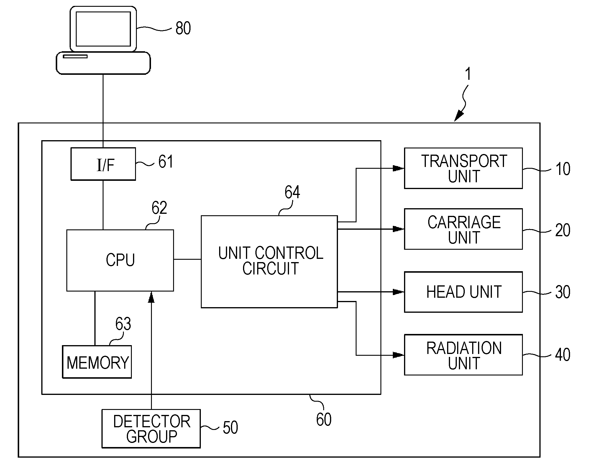
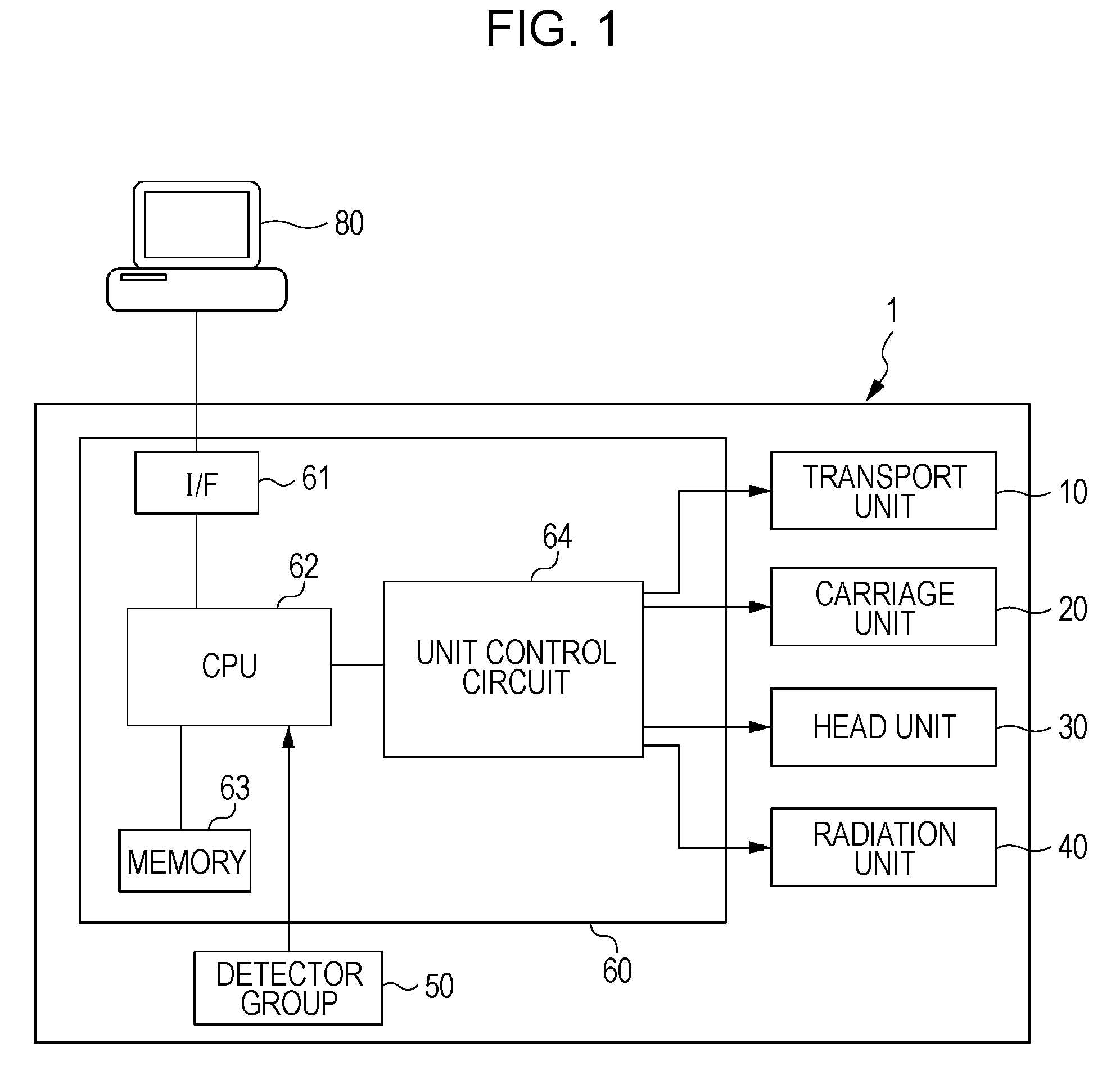
[0150]When a printing operation is executed by the user as he / she designates the transparent film as a medium and selects an image, which is supposed to be seen directly, using the computer 80, the printer driver generates printing data for printing a positive image of the designated image, and printing information related to printing in the surface printing mode is given to the printing data, which is then sent to the printer 1.
[0151]When the printer 1 receives the printing data and the printing information, the controller 60 executes a printing program for printing a positive image in the int...
third exemplary embodiment
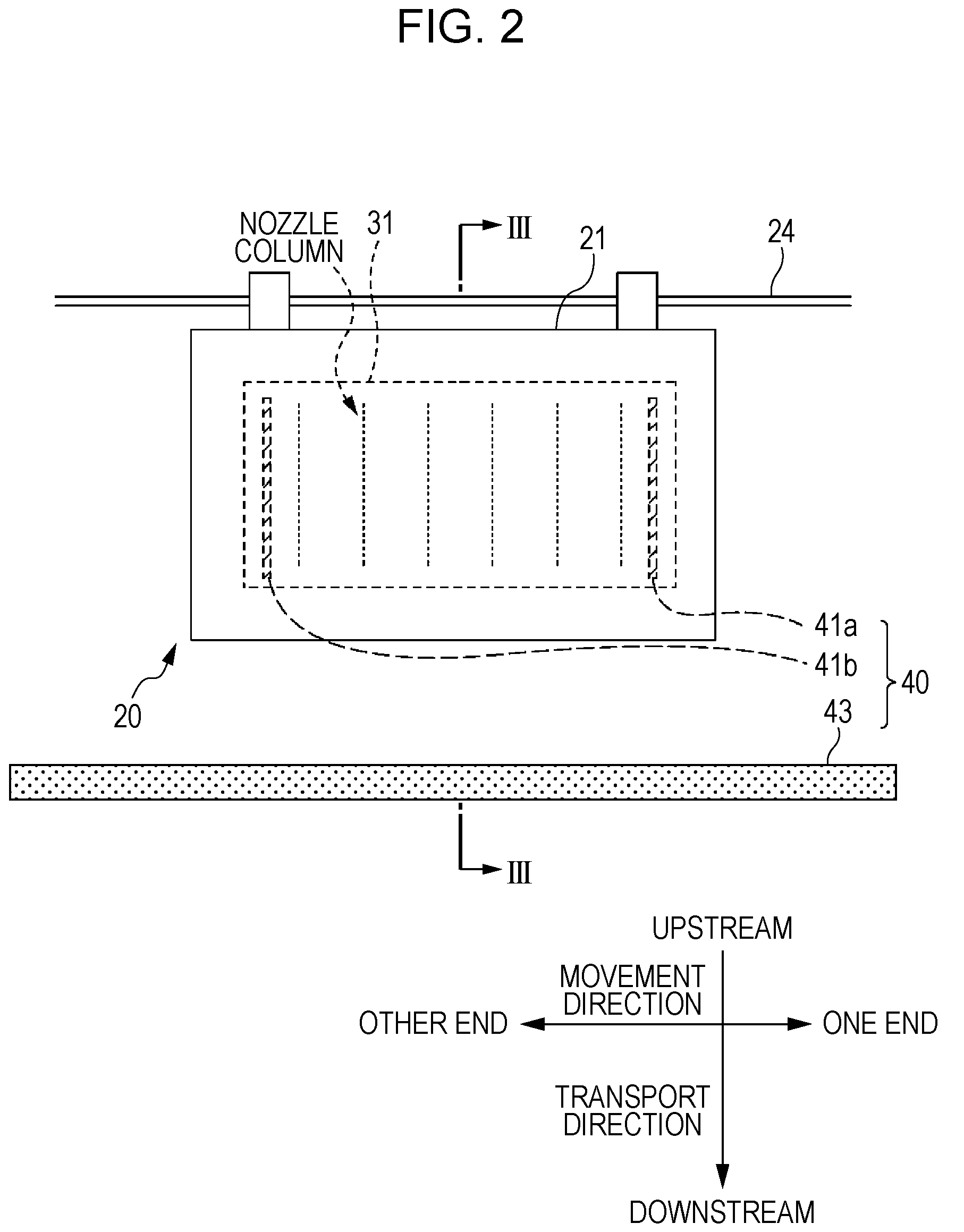
[0160]The third exemplary embodiment is an example in which the printing mode without overlapping is set to both the surface printing mode and the backside printing mode. The surface printing mode is set to eject ink when the carriage moves in one direction (i.e., a predetermined direction), and the backside printing mode is set to eject ink when the carriage moves in the predetermined direction and when the carriage moves in the opposite direction. That is, Uni-d printing mode is set to the surface printing mode, and Bi-d printing mode is set to the backside printing mode.
[0161]In the third exemplary embodiment, a printing operation is executed by the user as he / she designates the transparent film as a medium and selects an image, which is supposed to be seen directly, using the computer 80, the printer driver generates printing data for printing a positive image of the designated image, and printing information related to printing in the surface printing mode is given to the print...
PUM
 Abstract
Description
Claims
Application Information
 - R&D
- Intellectual Property
- Life Sciences
- Materials
- Tech Scout
- Unparalleled Data Quality
- Higher Quality Content
- 60% Fewer Hallucinations
Browse by: Latest US Patents, China's latest patents, Technical Efficacy Thesaurus, Application Domain, Technology Topic, Popular Technical Reports.
© 2025 PatSnap. All rights reserved.Legal|Privacy policy|Modern Slavery Act Transparency Statement|Sitemap|About US| Contact US: help@patsnap.com