Supercharge Your Innovation With Domain-Expert AI Agents!

Remote circuit locking switch system

a remote circuit and switch technology, applied in the direction of optical elements, instruments, digital transmission, etc., can solve the problems of information processing infrastructures being vulnerable to attack from anywhere in the data communication network, increasing security requirements, and increasing security threats

Inactive Publication Date: 2013-08-13
COMPANION DIAGNOSTICS
View PDF15 Cites 0 Cited by
  • Summary
  • Abstract
  • Description
  • Claims
  • Application Information

AI Technical Summary

Problems solved by technology

As the threat to information processing infrastructures continues to increase, the requirements for security become more demanding.
The weakness of such an approach is that the security system is vulnerable to attack from anywhere within the data communications network.

Method used


Image

  • Remote circuit locking switch system
  • Remote circuit locking switch system
  • Remote circuit locking switch system

Examples


Embodiment Construction

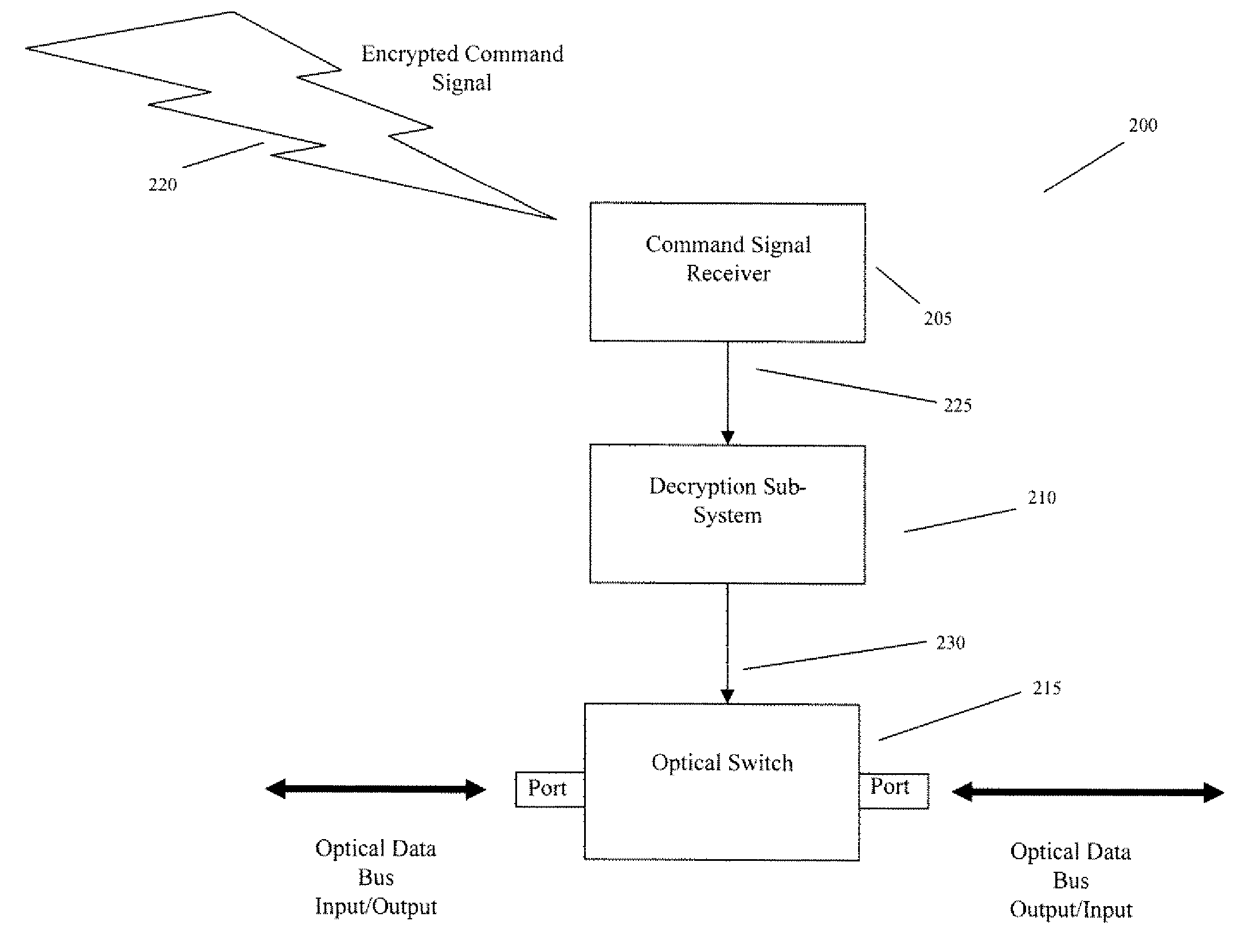
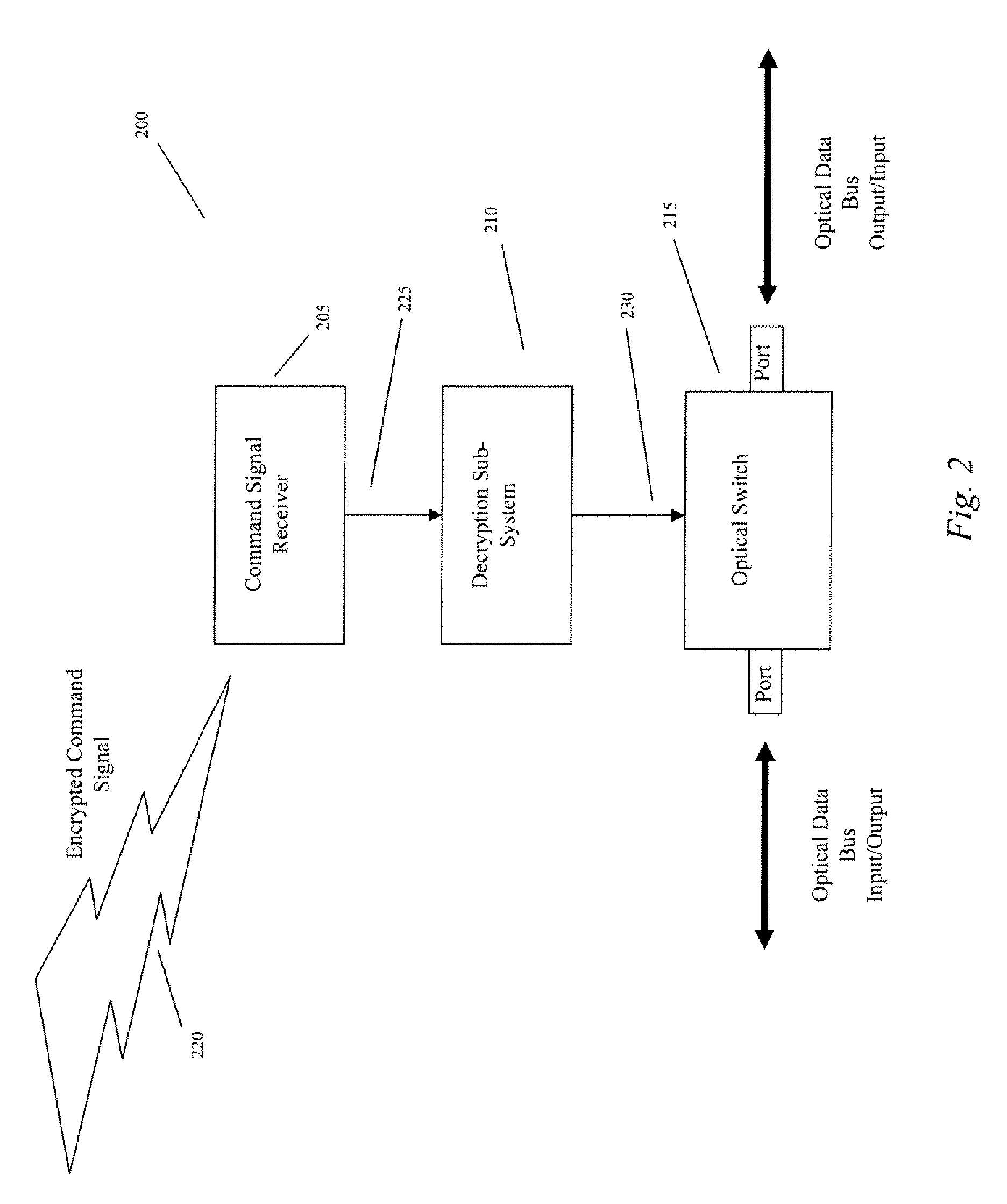
[0013]The Remote Circuit Locking system provides the ability to remotely activate or deactivate an information processing infrastructure. Activation or deactivation is independent of the infrastructures software operating system and is not vulnerable to software based hacking from points throughout the infrastructure network.

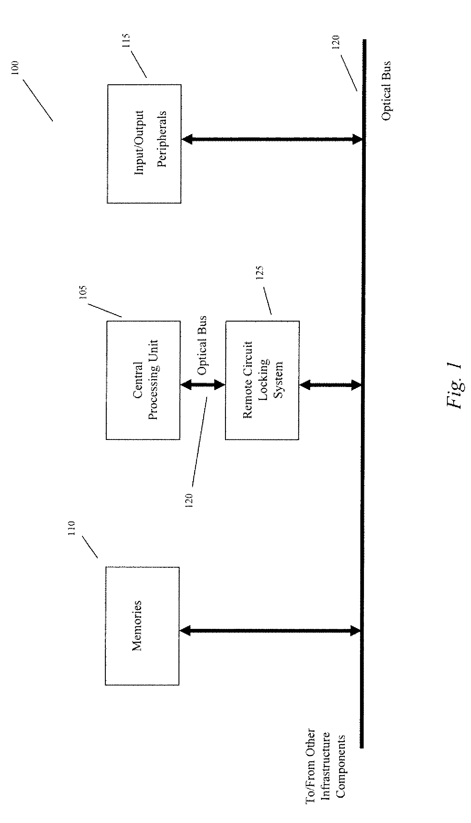
[0014]In an embodiment, a system and method is described which provides the capability of remotely controlling operation of a central processing unit or other component(s) of an information processing infrastructure. FIG. 1 schematically illustrates a block diagram of an information processing infrastructure 100 comprising a central processing unit 105, one or more electronic memories 110, multiple input / output peripheral devices 115, and an optical bus 120 operatively interconnecting each of component units. Optical bus technologies are widely employed to interconnect the infrastructure components. The various system components may either be locally or remotely...


PUM


Abstract

A method and apparatus for remotely controlling access to the components of an optically interconnected information processing infrastructure is presented. Access to the infrastructure is controlled independently of the infrastructure operating system.

Description

CROSS-REFERENCE TO RELATED APPLICATIONS[0001]This non-provisional patent application claims the benefit of U.S. Provisional Patent Application Ser. No. 61 / 166,460, filed Apr. 3, 2009, the entire disclosure of which is incorporated by reference in its entirety herein.BACKGROUND OF THE INVENTION[0002]The high data rate demands of modern information processing infrastructure have led to the use of optical data transmission technology for the interconnection of infrastructure components. As the threat to information processing infrastructures continues to increase, the requirements for security become more demanding. Computer systems, communications systems and traffic control systems, all of which are computer processor based, are examples of highly autonomous information processing infrastructures that require the highest level of protection from unauthorized access. In each of these systems, the various components of the infrastructure are accessed by one or more data communications ...

Claims


Application Information

Patent Timeline
Patent Type & Authority Patents(United States)
IPC IPC(8): H04K1/00
CPCH04B10/278H04L9/00G09C1/00G06F21/64H04L2209/12H04L2209/80
Inventor SELINFREUND, RICHARD H.BERRY, FRED
Owner COMPANION DIAGNOSTICS
Features
  • R&D
  • Intellectual Property
  • Life Sciences
  • Materials
  • Tech Scout
  • Unparalleled Data Quality
  • Higher Quality Content
  • 60% Fewer Hallucinations
Learn More