Supercharge Your Innovation With Domain-Expert AI Agents!

Hierarchical closed-loop control system for aircraft, missiles and munitions

a control system and hierarchical technology, applied in the direction of automatic actuation, navigation instruments, instruments, etc., can solve the problems of reducing the effective payload, the maximum achievable range, the lethality of missiles and aircraft, and the inability of conventional missile and aircraft control techniques to meet new multi-mission high accuracy, long-range fire requirements, etc., to achieve enhanced aerodynamic control, maneuverability and stabilization

Inactive Publication Date: 2013-10-01
ORBITAL RES
View PDF5 Cites 2 Cited by
  • Summary
  • Abstract
  • Description
  • Claims
  • Application Information

AI Technical Summary

Benefits of technology

Enhances aerodynamic performance by enabling real-time control of fluid flow, reducing weight and volume, and improving maneuverability and stability, while minimizing drag and cost.

Problems solved by technology

These control surfaces require significant volume to house the control actuation system, which includes heavy servomotors, thereby imposing significant limitations on the aircraft or missile's aerodynamic performance.
These hinged-control surfaces also reduce the effective payload, maximum achievable range, and lethality of missiles and aircraft.
Conventional missile and aircraft control techniques are not capable of meeting new multi-mission highly accurate, long-range fire requirements that are needed to ensure the multi-target engagement capabilities of missiles or aircraft, particularly “smart” missiles and aircraft.
The major disadvantages of traditional control surfaces is space restriction, i.e., control surfaces must be located in an annular space around the throat of the propulsion nozzle; increased weight; and drag from exposed surfaces.
The conventional control surfaces necessitate hinges, which increase the overall weight induced aerodynamic drag and also the complexity of the propulsion system.
Such open-loop flow control systems fail to maintain the required aerodynamic performance of the air vehicle under dynamic conditions.

Method used


Image

  • Hierarchical closed-loop control system for aircraft, missiles and munitions
  • Hierarchical closed-loop control system for aircraft, missiles and munitions
  • Hierarchical closed-loop control system for aircraft, missiles and munitions

Examples


Embodiment Construction

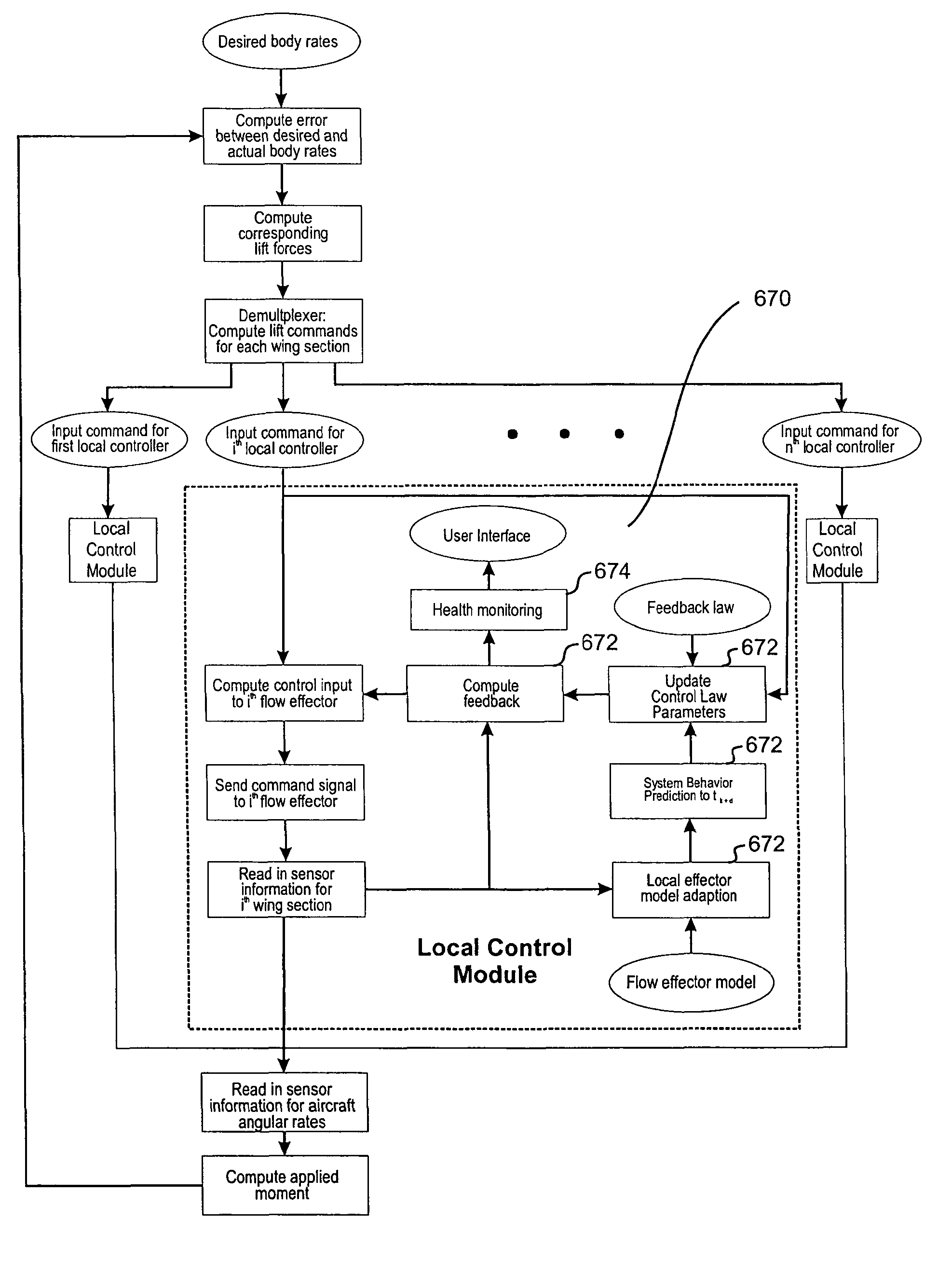
[0060]The present invention relates to a missile or aircraft with a hierarchical, closed-loop flow control system and more particularly to aircraft or missile with a flow control system for aerodynamic control, maneuverability and stabilization. The present invention further relates to a method of operating the flow control system. The present invention involves the airflow control or flow control on any aerodynamic surface, aerodynamically-coupled surfaces or any combination of aerodynamic surfaces on a missile or aircraft including but not limited to lift surface control, forebody control, afterbody control and any combination thereof. The forebody herein is described as the front half of the missile or aircraft or that portion in front of the lift surfaces, i.e., the wings. Preferably, the forebody is the front 25% of the length of the missile or aircraft, and most preferably the forebody is the nose of the missile or aircraft. The nose of the missile or aircraft is the cone shap...


PUM


Abstract

The present invention relates to a missile or munition with a hierarchical, modular, closed-loop flow control system, more particularly to aircraft or munition with flow control system for enhanced aerodynamic control, maneuverability and stabilization. The present invention further relates to a method of operating the flow control system.Various embodiments of the flow control system involve elements including flow sensors, active flow control devices or activatable flow effectors, and logic devices with closed loop control architecture. The sensors are used to estimate or determine flow conditions on the surfaces of a missile or munition. The active flow control device or activatable flow effectors create on-demand flow disturbances, preferably micro-disturbances, at different points along the various aerodynamic surfaces of the missile or aircraft to achieve a desired stabilization or maneuverability effect. The logic devices are embedded with a hierarchical control structure allowing for rapid, real-time control at the flow surface.

Description

CROSS REFERENCE TO RELATED APPLICATIONS[0001]This application is a continuation of co-pending U.S. patent application Ser. No. 12 / 557,599, which was filed on Sep. 11, 2009, which is a continuation of patent application Ser. No. 11 / 311,767 filed on Dec. 19, 2005, currently pending, which is a continuation of U.S. patent application Ser. No. 10 / 725,266 filed on Dec. 1, 2003, currently pending, which is a continuation-in-part of U.S. patent application Ser. No. 10 / 336,117 filed on Jan. 3, 2003 which issued as U.S. Pat. No. 6,685,143 on Feb. 3, 2004.[0002]The U.S. Government has a paid-up license in this invention and the right in limited circumstances to require the patent owner to license others on reasonable terms provided for by the terms of grant number F33615-02-M-32217 awarded by the United States Air Force.BACKGROUND OF THE INVENTION[0003]1. Field of the Invention[0004]The present invention relates to a missile or aircraft with a hierarchical closed-loop flow control system and ...

Claims


Application Information

Patent Timeline
Patent Type & Authority Patents(United States)
IPC IPC(8): B64C13/00F41G7/00G01C23/00
CPCG05D1/107F42B10/38F42B10/40F42B10/42F42B10/668F42B15/01
Inventor PRINCE, TROY S.KOLACINSKI, RICHARDPATEL
Owner ORBITAL RES
Features
  • R&D
  • Intellectual Property
  • Life Sciences
  • Materials
  • Tech Scout
  • Unparalleled Data Quality
  • Higher Quality Content
  • 60% Fewer Hallucinations
Learn More