Check patentability & draft patents in minutes with Patsnap Eureka AI!

Tape measure apparatus with a rotating and sliding catch

a technology of sliding catch and tape measure, which is applied in the field of tape measure apparatus, can solve the problems of irritating users, rewinding the rule blade, and restricted utility of tape measure apparatus

Active Publication Date: 2013-11-26
RICALDE PAUL
View PDF46 Cites 5 Cited by
  • Summary
  • Abstract
  • Description
  • Claims
  • Application Information

AI Technical Summary

Problems solved by technology

Tape measures are well adapted for measuring distances but their utility is usually restricted to this single function.
However, since the catches or end hooks are used to grab / hook onto an edge portion of an article being measured, and the rule blade pulled out to the second dimension being measured, small area catches / end hooks make it difficult to grab / hook onto the article being measured with the catches / end hooks tending to slide away causing rewinding of the rule blade and irritation to the user.
Additionally, because conventionally available catches / end hooks point downwardly relative to the tops of rule blades, measurements requiring grabbing / hooking by the catches are limited to situations where the rule blade is facing up.
This situation makes it inconvenient for users wishing to grab / hook onto the underside edge of an object to be measured.
In certain instances the catches or end hooks to tape measures actually inhibit proper measurements.

Method used


Image

  • Tape measure apparatus with a rotating and sliding catch
  • Tape measure apparatus with a rotating and sliding catch
  • Tape measure apparatus with a rotating and sliding catch

Examples


Embodiment Construction

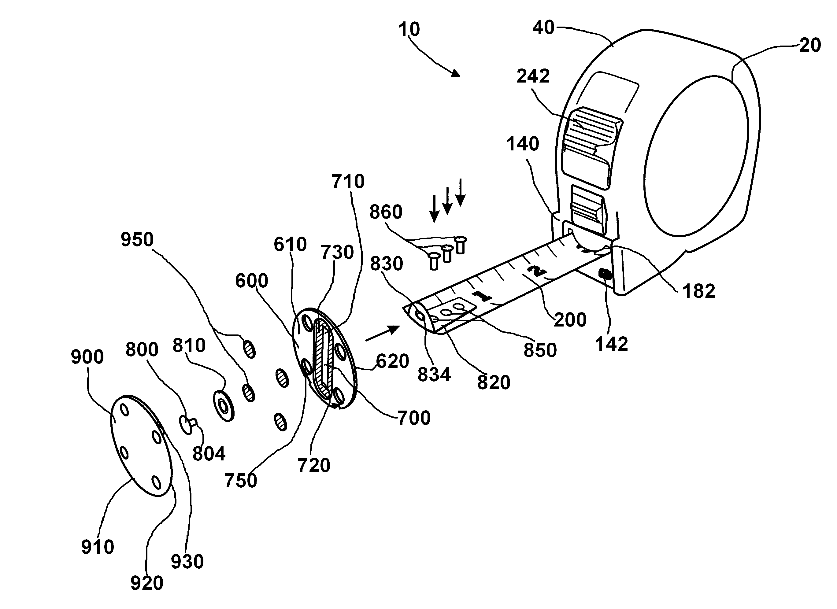
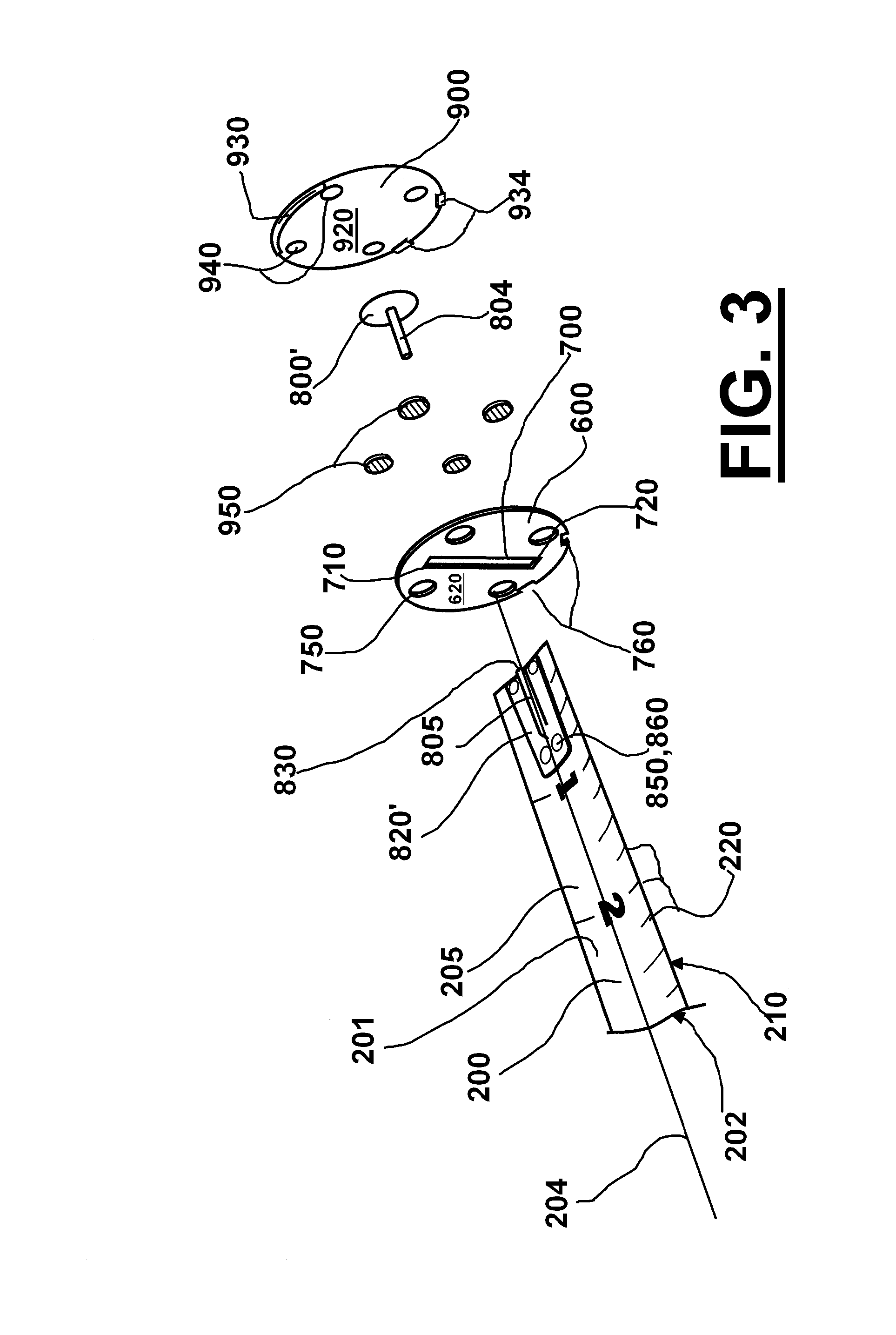
[0057]One embodiment provides a tape measure apparatus 10 which can include a conventional type tape measure 20 comprising a casing 40 having two side walls 60, a top wall 80, a bottom wall 100, a rear wall 120 and a front wall 140 defining enclosure 160. Front wall 140 has a rule blade aperture 180 adjacent to bottom wall 100.

[0058]Rule blade 200 is normally retractably stored in a coiled condition within enclosure 160 of casing 40. An inner end 205 of rule blade 200 is secured within enclosure 160, while an outer end 210 of rule blade 200 protrudes through blade aperture 180 in casing 40. A lock and automatic rewind switch 240 can be carried on top wall 80 or front wall 140 of casing 40, to keep a portion of rule blade 200 in an extended locked position through blade aperture 180 in casing 40. Switch 240 is manually operated to retract rule blade 200 into enclosure 160 of casing 40.

[0059]Rule blade 200 is elongated, slightly concave and fabricated out of a substantially strong and...


PUM


Abstract

An improved tape measure apparatus which includes a catch that is both slidable and rotatable relative to the rule blade in a plane which is perpendicular to the longitudinal axis of the rule blade when the rule blade is extended from the tape casing.

Description

CROSS-REFERENCE TO RELATED APPLICATIONS[0001]Not applicableSTATEMENT REGARDING FEDERALLY SPONSORED RESEARCH OR DEVELOPMENT[0002]Not applicableREFERENCE TO A “MICROFICHE APPENDIX”[0003]Not applicableBACKGROUND[0004]One embodiment relates generally to carpentry tools and, more specifically, to an improved tape measure apparatus which includes a rotating and sliding catch.[0005]Standard tape measures include a length of tape wound on a spool with a spring return mechanism so that after the tape is taken out of a housing, the spring return mechanism automatically retracts the tape into the housing. A locking mechanism, typically a sliding button, locks the tape for the purpose of reading the length of the deployed tape.[0006]Numerous tape measures have been provided in prior art. For example, U.S. Pat. No. 2,624,120 to Mills; U.S. Pat. No. 4,574,486 to Drechsler; and U.S. Pat. No. 5,390,426 to Hull are illustrative of the prior art and incorporated herein by reference to show the conven...

Claims


Application Information

Patent Timeline
Patent Type & Authority Patents(United States)
IPC IPC(8): G01B3/10
CPCG01B3/1056
Inventor RICALDE, PAUL
Owner RICALDE PAUL
Features
  • R&D
  • Intellectual Property
  • Life Sciences
  • Materials
  • Tech Scout
  • Unparalleled Data Quality
  • Higher Quality Content
  • 60% Fewer Hallucinations
Learn More