Supercharge Your Innovation With Domain-Expert AI Agents!

Electric continuous variable valve timing apparatus

a timing apparatus and continuous variable technology, applied in mechanical equipment, valve arrangements, machines/engines, etc., can solve the problems of excessive exhaust gas generation, inability to obtain relative phase change of camshafts, and inability to anticipate rapid and accurate control, etc., to reduce the entire length of the apparatus

Active Publication Date: 2013-12-31
HYUNDAI MOTOR CO LTD
View PDF8 Cites 0 Cited by
  • Summary
  • Abstract
  • Description
  • Claims
  • Application Information

AI Technical Summary

Benefits of technology

This solution enables precise valve timing control independent of engine oil pressure, reduces power consumption, and simplifies the manufacturing process, enhancing engine efficiency and reducing costs by eliminating the need for hydraulic pressure and simplifying the apparatus design.

Problems solved by technology

The vane-type variable valve timing apparatus, however, uses lubrication oil of an engine, and thus, when oil pressure is low, rapid and accurate control cannot be expected.
Particularly, in idle state, in high temperature, in start condition and so on, when engine oil pressure is not sufficient, relative phase change of a camshaft cannot be obtained, and excessive exhaust gas is generated.
While an electric variable valve timing apparatus may overcome the drawbacks, however for maintaining valve timing which is controlled, power consumption continues and entire length of the apparatus has to be lengthened.

Method used


Image

  • Electric continuous variable valve timing apparatus
  • Electric continuous variable valve timing apparatus
  • Electric continuous variable valve timing apparatus

Examples


Embodiment Construction

[0040]Reference will now be made in detail to various embodiments of the present invention(s), examples of which are illustrated in the accompanying drawings and described below. While the invention(s) will be described in conjunction with exemplary embodiments, it will be understood that the present description is not intended to limit the invention(s) to those exemplary embodiments. On the contrary, the invention(s) is / are intended to cover not only the exemplary embodiments, but also various alternatives, modifications, equivalents and other embodiments, which may be included within the spirit and scope of the invention as defined by the appended claims.

[0041]Exemplary embodiments of the present invention will hereinafter be described in detail with reference to the accompanying drawings.

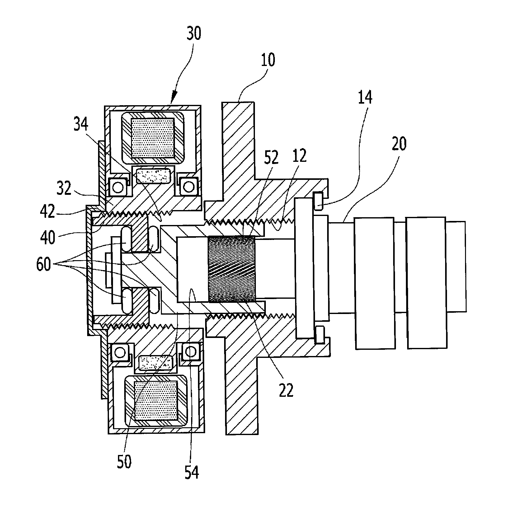
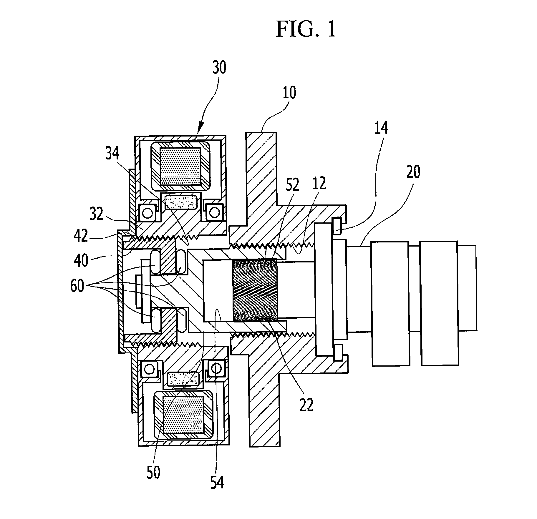
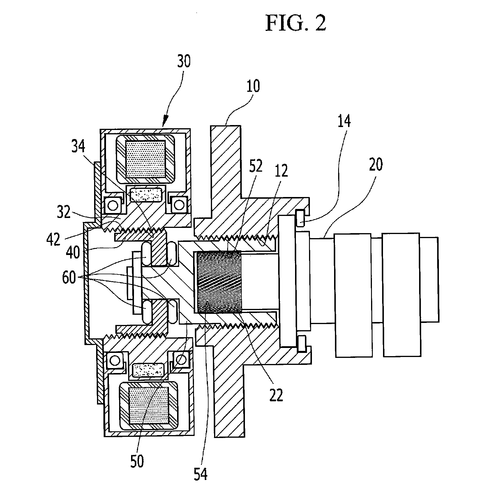
[0042]FIG. 1 and FIG. 2 are cross-sectional views of an electric continuously variable valve timing apparatus according to the first exemplary embodiment of the present invention, and FIG. 3 is a...


PUM


Abstract

An electric continuously variable valve timing apparatus may include a cam sprocket, a camshaft rotatably connected with the cam sprocket, a motor portion, a lead screw portion which may be disposed within the motor portion, may be screwed-engaged with the motor portion, and moves along length direction of the camshaft according to operations of the motor portion, and a camshaft holder rotatably connecting the lead screw portion and the cam sprocket, wherein the camshaft holder moves along length direction of the camshaft according to the movement of the lead screw portion and varies relative phase angle between the cam sprocket and the camshaft for controlling valve timing.

Description

CROSS-REFERENCE TO RELATED APPLICATION[0001]The present application claims priority to Korean Patent Application No. 10-2011-0048728 filed in the Korean Intellectual Property Office on May 23, 2011, the entire contents of which is incorporated herein for all purposes by this reference.BACKGROUND OF THE INVENTION[0002]1. Field of the Invention[0003]The present invention relates to a continuously variable valve timing apparatus. More particularly, the present invention relates to an electric continuously variable valve timing apparatus of which entire length may be reduced and engine layout may be simplified.[0004]2. Description of Related Art[0005]Generally, a continuously variable valve timing apparatus (CVVT or Camshaft phaser) is a device which may adjust the timing of the opening and closing of valves.[0006]A general continuously variable valve timing apparatus, usually used in vehicle makers, i.e. a vane-type variable valve timing apparatus, needs relatively small volume and is ...

Claims


Application Information

Patent Timeline
Patent Type & Authority Patents(United States)
IPC IPC(8): F01L1/34
CPCF01L2001/3522F01L1/344F01L1/34
Inventor YANG, JEI CHOONCHOI, BYONG YOUNGKONG, JIN KOOKWOO, SOO HYUNGWON, YOUNG JINKIM, JIN SOON
Owner HYUNDAI MOTOR CO LTD
Features
  • R&D
  • Intellectual Property
  • Life Sciences
  • Materials
  • Tech Scout
  • Unparalleled Data Quality
  • Higher Quality Content
  • 60% Fewer Hallucinations
Learn More