Supercharge Your Innovation With Domain-Expert AI Agents!

Flexible drive for breast pump

a breast pump and flexible technology, applied in the field of breast pumps, can solve the problems of creating mechanical noise, unfavorable breast pump use, and uncomfortable for mothers to use breasts

Active Publication Date: 2013-12-31
KONINK PHILIPS ELECTRONICS NV
View PDF6 Cites 3 Cited by
  • Summary
  • Abstract
  • Description
  • Claims
  • Application Information

AI Technical Summary

Benefits of technology

The solution provides a more comfortable and quiet breast pump operation by minimizing friction and noise, enhancing energy efficiency and manufacturing tolerances, and allowing for compact design with reduced motor and gearbox vibration transmission.

Problems solved by technology

However, it can be unpleasant and / or uncomfortable for a mother to use a breast pump as it can feel unnatural since the device may feel and sound overly ‘mechanical’.
Therefore, the discomfort and / or unnatural feel of using the breast pump may not put the mother at ease and may make her feel anxious, thereby affecting her capability to express milk for her baby.
Furthermore, the above-mentioned known mechanisms for negative pressure creation in known breast pumps include sliding surfaces and / or frictional contact which produce wear and / or may require lubrication to minimize wear.
These mechanisms may create mechanical noise themselves and can also effectively transmit vibrations of the motor and gearbox to the outside structure of the breast pump such as the housing and / or milk collection bottle.

Method used


Image

  • Flexible drive for breast pump
  • Flexible drive for breast pump
  • Flexible drive for breast pump

Examples


first embodiment

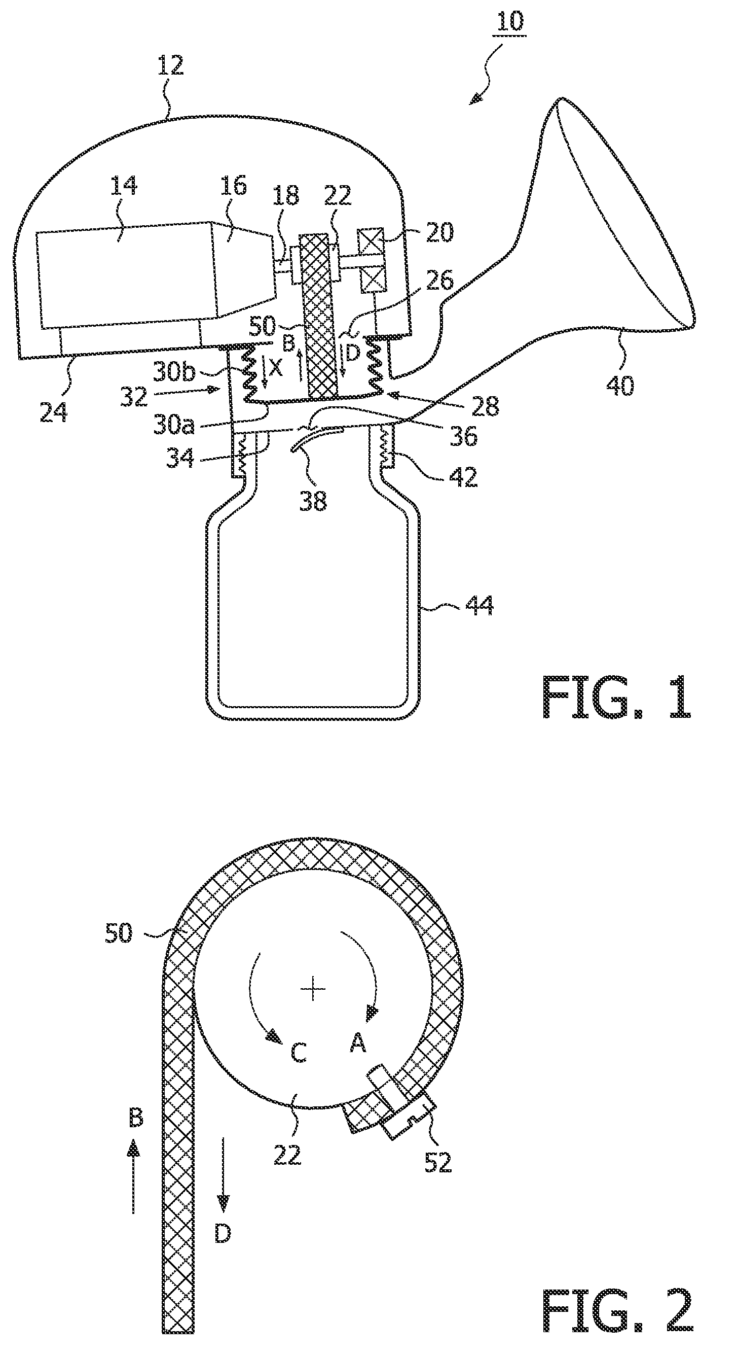
[0024]Referring now to FIGS. 1 and 2, a breast pump 10 incorporating a drive mechanism of the invention is shown and comprises a housing 12 containing a drive motor 14 coupled to a reduction gearbox 16. A drive shaft 18 extends from the gearbox 16 and is supported at its distal end in a support bearing 20. A drive wheel 22 is mounted on the drive shaft 18 between the gearbox 16 and the support bearing 20.

[0025]The housing 12 includes a base 24 on which the motor 14 and support bearing 20 are mounted, and the base 24 has an aperture 26 extending there through. The aperture 26 is sealed closed on the outside of the housing 12 by a resilient membrane 28 comprising a disc portion 30a and a bellows section 30b extending between a peripheral edge of the disc portion 30a and the base 24 of the housing 12 around the aperture 26.

[0026]A vacuum chamber 32 is coupled to the base 24 of the housing 12 over the aperture 26 and resilient membrane 28 so that the resilient membrane 28 extends into t...

second embodiment

[0037]the invention further comprises a second resilient membrane 129 which is disposed on the outside of the base 124 of the housing 112 around the aperture 126. The second resilient membrane 129 is sealed around the aperture 126 such that a closed intermediate cavity is 133 is defined between the first and second resilient membranes 128,129.

[0038]A vacuum chamber 132 is coupled to the base 124 of the housing 112 over the aperture 126 and second resilient membrane 129 so that the second resilient membrane 129 extends into the vacuum chamber 132. The vacuum chamber 132 is of a generally cylindrical shape with one end of the cylindrical chamber being coupled to the housing 112 and sealed around the aperture 126 as described above, and the other end of the cylindrical chamber having a bottom wall 134. A breast-receiving funnel 140 extends from one side of the cylindrical side wall of the vacuum chamber 132 and is in fluid communication with the vacuum chamber 132. The bottom wall 134 ...


PUM


Abstract

A drive mechanism for generating a negative pressure in a vacuum chamber (32 / 132) of a breast pump (10 / 110), the drive mechanism comprising a housing (12 / 112), a motor (14 / 114) coupled to a rotatable drive element within the housing, a resilient membrane (28 / 128) coupled to the housing and, a flexible strap (50 / 150) coupled between the drive element and the resilient membrane. Rotation of the drive element causes the flexible strap to pull and resiliently deform the resilient membrane to create the negative pressure in a vacuum chamber of a breast pump. Also, a breast pump including such a drive mechanism together with a vacuum chamber (32 / 132) coupled to the housing (12 / 112). The vacuum chamber comprises a receptacle and a breast-receiving funnel (40 / 140) in fluid communication with the receptacle, wherein when a woman's breast is placed in the breast-receiving funnel, the vacuum chamber is sealed closed such that deformation the resilient membrane (28 / 128) creates a negative pressure in the vacuum chamber.

Description

FIELD OF THE INVENTION[0001]The invention relates to breast pumps, and more specifically to drive mechanisms for vacuum creation in breast pumps and breast pumps incorporating such drive mechanisms.BACKGROUND OF THE INVENTION[0002]A breast pump is a device used by mothers for expressing their breast milk into a baby feeding bottle. Such devices can be either manually operated or automated by incorporation of, for example, an electric motor to drive the device. Such devices often include a flexible membrane which is moved up and down to create a negative pressure in a vacuum chamber of the breast pump, and include a rack and pinion mechanism in which the pinion rotates back and forth to move the rack, which is connected to the membrane, linearly back and forth to generate the negative pressure. Alternatively, a crank shaft or cam / eccentric element may be employed to move the membrane back and forth to generate the negative pressure.[0003]It is known that the hormoneprolactin’ which...

Claims


Application Information

Patent Timeline
Patent Type & Authority Patents(United States)
IPC IPC(8): A61M1/06
CPCA61M2001/0072F04B45/02F04B45/027A61M1/06A61M1/0072A61M1/82
Inventor TACK, JOHANNES, WILLEM
Owner KONINK PHILIPS ELECTRONICS NV
Features
  • R&D
  • Intellectual Property
  • Life Sciences
  • Materials
  • Tech Scout
  • Unparalleled Data Quality
  • Higher Quality Content
  • 60% Fewer Hallucinations
Learn More