Supercharge Your Innovation With Domain-Expert AI Agents!

Jaw set with serrated cutting blades

a technology of cutting blades and blades, which is applied in the field of jaw sets, can solve the problems of premature wear and inefficient manner of doing so, and achieve the effect of maximum blade strength

Active Publication Date: 2014-02-11
RAMUN MICHAEL R RAMU +1
View PDF44 Cites 5 Cited by
  • Summary
  • Abstract
  • Description
  • Claims
  • Application Information

AI Technical Summary

Benefits of technology

The serrated blade inserts significantly extend the life of the blades by 80-90% compared to traditional smooth blades, provide a cleaner cut, and reduce the effort required to cut wire cables by unraveling and shredding them, while minimizing wear and stress on the blades and other components.

Problems solved by technology

While this configuration is capable of cutting small diameter pipe P and, additionally, wire cable, as illustrated for pipe in FIG. 2, the manner by which it does so is not efficient and results in premature wear.

Method used


Image

  • Jaw set with serrated cutting blades
  • Jaw set with serrated cutting blades
  • Jaw set with serrated cutting blades

Examples


Embodiment Construction

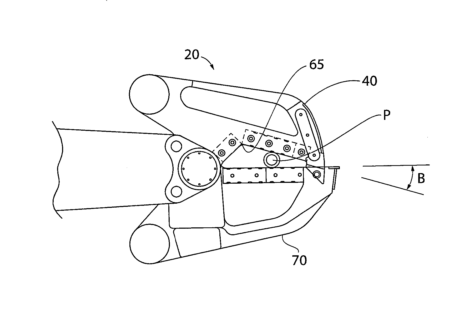
[0024]The inventors have discovered that by changing the configuration of the blade inserts in the jaw set, it is possible to cause the cutting of a small diameter pipe or a wire cable to occur at different locations along the first jaw blade and the second jaw blade and to minimize or prevent the cutting of such items at the apex location. By utilizing different areas of the first jaw blade and the second jaw blade for cutting, not only is the blade wear at the apex minimized or eliminated, but, furthermore, by distributing the cutting along different parts of the jaw blades, the life of the blade inserts may be significantly extended while, at the same time, maintaining a high quality cut. The modification of the subject invention relative to the prior art is the substitution of one or more blade inserts within the jaw blades to provide serrated blade inserts as opposed to smooth blade inserts. In particular, the inventors have discovered that by providing serrated blade inserts w...


PUM


Abstract

A jaw set utilizes blade inserts having serrated surfaces which draw in to capture and cut material prior to the material becoming trapped in the apex of the blade arrangement, thereby maximizing efficiency of the cutting operation. The subject invention is also directed to an individual blade insert having grooves that are longitudinally offset from bolt holes used to retain the blade insert within a jaw set.

Description

BACKGROUND OF THE INVENTION[0001]1. Field of the Invention[0002]The present invention relates to a jaw set used in demolition and recycling equipment. More particularly, the present invention relates to a jaw set having serrated blade inserts to provide for efficient cutting of wire cable, small diameter pipe, and the like.[0003]2. Description of Related Art[0004]While the present invention relates to demolition and recycling equipment, this equipment is also referred to as construction equipment and scrap handling / processing equipment. The description of demolition equipment, recycling equipment, scrap handling equipment, or construction equipment is not intended to be restrictive to the equipment being referenced.[0005]In the dismantling of an industrial site, wire cable and small diameter pipes are often encountered. FIG. 1 is prior art and illustrates a shear attachment 10 having a jaw set 20 made up of a first jaw 25 and a second jaw 30 which rotates relative to the first jaw 2...

Claims


Application Information

Patent Timeline
Patent Type & Authority Patents(United States)
IPC IPC(8): B02C9/04A01D34/00
CPCE02F9/2883E04G23/082E02F3/965
Inventor RAMUN, MICHAEL RICHARDRAMUN, JOHN R.
Owner RAMUN MICHAEL R RAMU
Features
  • R&D
  • Intellectual Property
  • Life Sciences
  • Materials
  • Tech Scout
  • Unparalleled Data Quality
  • Higher Quality Content
  • 60% Fewer Hallucinations
Learn More