Check patentability & draft patents in minutes with Patsnap Eureka AI!

Method for forming self-aligned overlay mark

a mask and overlay technology, applied in the field of self-aligning masks, can solve the problems of difficult to keep, and certain unwanted features are formed

Active Publication Date: 2014-03-04
NAN YA TECH
View PDF7 Cites 1 Cited by
  • Summary
  • Abstract
  • Description
  • Claims
  • Application Information

AI Technical Summary

Benefits of technology

This method ensures accurate overlay measurements and prevents interference from non-critical features, maintaining alignment precision and allowing for the transfer of critical pitch-doubled patterns into the substrate without misalignment, enabling precise registration and error quantification.

Problems solved by technology

It is challenging to keep each different feature from interfering with one another in the manufacturing process.
There are also certain unwanted features formed during the pitch doubling process.
In a process where a mask pattern is required to be formed in close proximity to the array features, the problem arises of how to measure the location of critical features such as the array features formed of a denser line / space patterns without the measurement being impacted by the adjacent non-critical pattern of the mask.

Method used


Image

  • Method for forming self-aligned overlay mark
  • Method for forming self-aligned overlay mark
  • Method for forming self-aligned overlay mark

Examples


Embodiment Construction

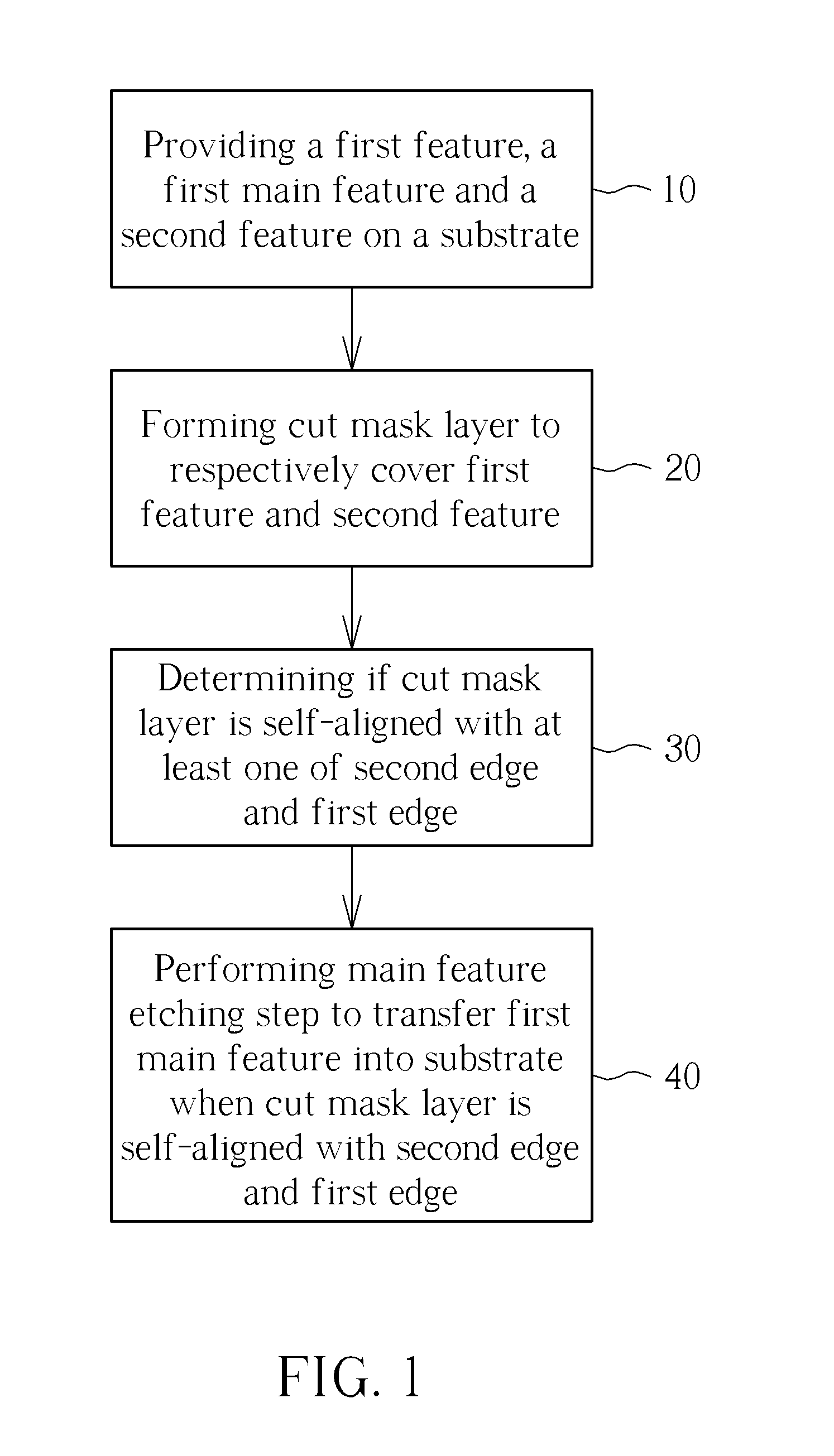
[0033]One aspect of the present invention provides a method for forming a protective mask on a substrate to create a self-aligned overlay mark without jeopardizing the alignment precision of a previously formed feature. In another aspect, the present invention also proposes a method to solve the problem of how to measure the location of features formed of a critical pattern without the measurement being impacted by another non-critical feature of a later formed mask.

[0034]FIG. 1 illustrates the method for forming a self-aligned overlay mark of the present invention. As shown in FIG. 5A, first a substrate 101 is provided (step 10). There are certain regions and features disposed on the substrate 101. For example, there are a first region 110, a second region 120, and a main feature 130 including a line / space array pattern 131 disposed on the substrate 101, as shown in FIG. 1. FIG. 5A illustrates a top view of the substrate 101 with the first region 110, the second region 120, the mai...


PUM


Abstract

A method for forming a self-aligned overlay mark is disclosed. First, a first region, a second region and a main feature which is disposed between the first region and the second region all disposed on the substrate are provided. The first region defines a first edge and the second region defines a second edge. Second, a cut mask layer is formed to respectively cover the first region and the second region to expose the main feature. Next, the cut mask layer is determined if it is self-aligned with the second edge or the first edge, and creates a self-aligned overlay mark. Later, a main feature etching step is carried out to transfer the main feature into the substrate when the cut mask layer is determined to be self-aligned with the second edge or the first edge.

Description

BACKGROUND OF THE INVENTION[0001]1. Field of the Invention[0002]The present invention generally relates to a method for forming a self-aligned mask with respect to a previously formed critical feature on a substrate. In particular, the present invention is directed to a method for forming a non-critical mask layer with respect to a previously formed critical feature and determining if the non-critical mask layer is self-aligned with the previously formed critical feature to serve as a self-aligned overlay mark at the same time.[0003]2. Description of the Prior Art[0004]Fabrication of silicon based memory chips usually involves multiple photolithographic processing steps. In each of these steps, a particular pattern with certain fixed dimensions is printed on the wafer. After all of the particular patterns are processed, a complete working circuit is created. It is very critical that each particular pattern is overlaid on top of a prior reference particular pattern within a certain t...

Claims


Application Information

Patent Timeline
Patent Type & Authority Patents(United States)
IPC IPC(8): H01L21/76
CPCG03F1/42G03F7/70633
Inventor NAIR, VINAYPRATT, DAVIDHAWK, CHRISTOPHERHOUSLEY, RICHARD
Owner NAN YA TECH
Features
  • R&D
  • Intellectual Property
  • Life Sciences
  • Materials
  • Tech Scout
  • Unparalleled Data Quality
  • Higher Quality Content
  • 60% Fewer Hallucinations
Learn More