Check patentability & draft patents in minutes with Patsnap Eureka AI!

Driving circuit and liquid crystal display module having the same

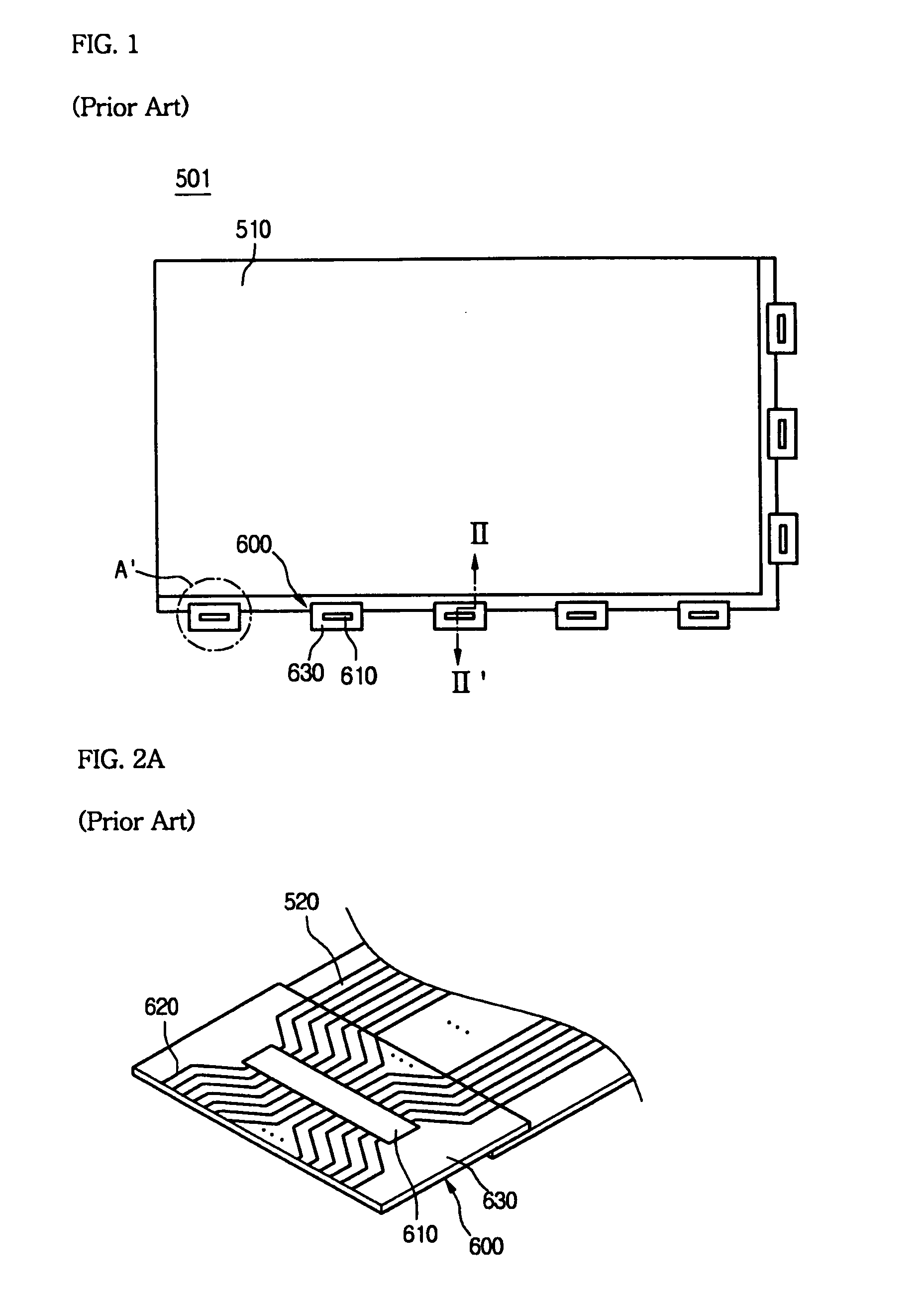
a technology of driving circuit and liquid crystal display module, which is applied in non-linear optics, instruments, optics, etc., can solve the problems of easy damage to circuit lines formed on damage to pcb b>700/b> and/or the driving circuit b>600/b>, etc., to suppress damage caused by stress, vibration, impa

Active Publication Date: 2014-03-11
LG DISPLAY CO LTD
View PDF15 Cites 2 Cited by
  • Summary
  • Abstract
  • Description
  • Claims
  • Application Information

AI Technical Summary

Benefits of technology

[0022]An object of the present invention is to provide a driving circuit capable of suppressing damage caused by stress, vibration, impact, and the like.

Problems solved by technology

However, when the driving circuit 600 is folded or bent, the circuit lines 620 formed on the driving circuit 600 may be damaged or cut.
Otherwise, when vibration and impact are applied to the PCB 700 and / or the driving circuit 600, the PCB 700 and / or the driving circuit 600 may be easily damaged.

Method used


Image

  • Driving circuit and liquid crystal display module having the same
  • Driving circuit and liquid crystal display module having the same
  • Driving circuit and liquid crystal display module having the same

Examples


Embodiment Construction

[0037]Reference will now be made in detail to the embodiments of the present invention, examples of which are illustrated in the accompanying drawings. Wherever possible, the same reference numbers will be used throughout the drawings to refer to the same or like parts.

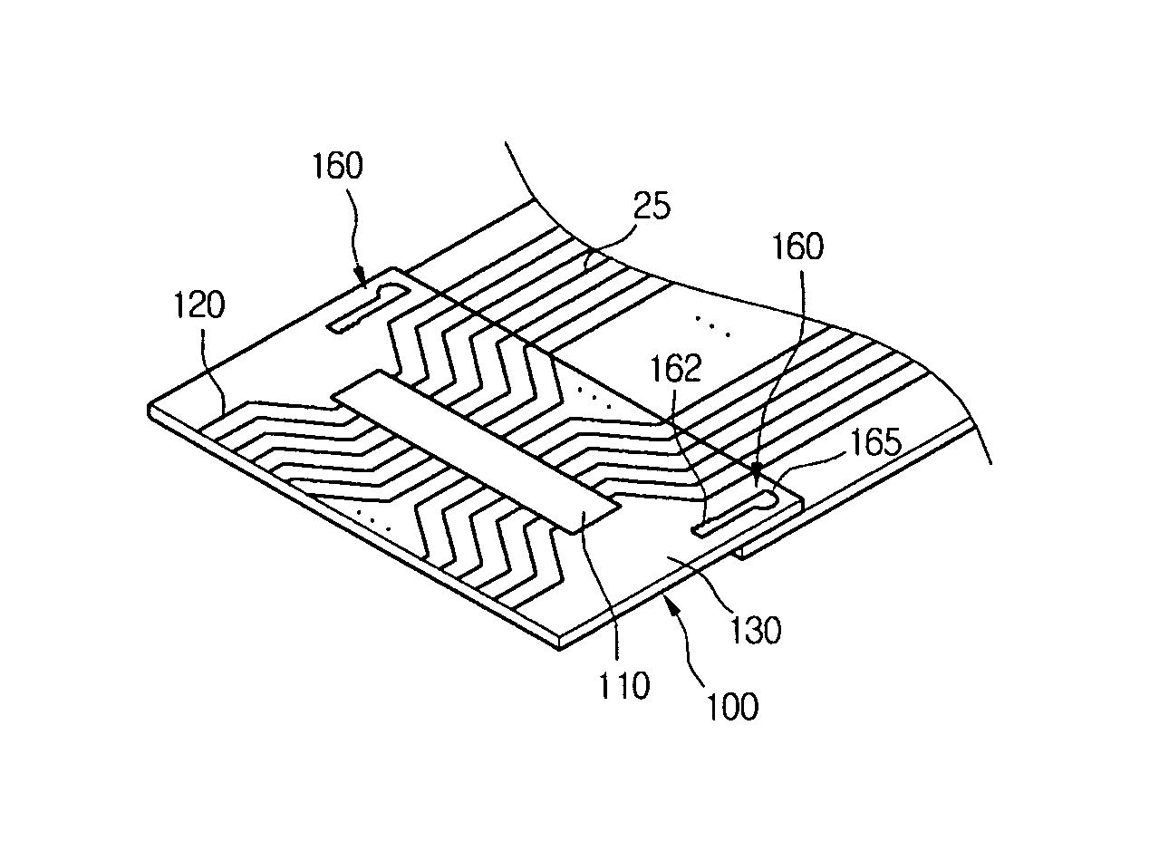
[0038]FIG. 4 is a plan view illustrating an LCD module according to an embodiment of the present invention. FIG. 5A is an enlarged view illustrating part of a driving circuit in FIG. 4, and FIG. 5B is a cross-sectional view taken along line V-V′ in FIG. 4.

[0039]Referring to FIGS. 4, 5A, and 5B, a liquid crystal display (LCD) module 1 includes an LCD panel 10 having a display device for displaying an image, a printed circuit board (PCB) 200 processing an image signal generated from an information processing device and generating a driving signal, and a driving circuit 100 providing a driving signal to the LCD panel 10.

[0040]The LCD panel 10 includes an effective pixel region (EPR), and a non-effective pixel region (NEP...


PUM

PropertyMeasurementUnit
areaaaaaaaaaaa
stressaaaaaaaaaa
zigzag shapeaaaaaaaaaa

Abstract

A driving circuit of a liquid crystal display module includes a substrate, a driving chip, a plurality of circuit lines connected to the driving chip, and a dummy pattern disposed outside the circuit lines parallel thereto. The liquid crystal display module includes a display panel, and a driving circuit. The display panel includes an effective pixel region, a non-effective pixel region, a display device displaying an image in the effective pixel region, and signal lines connected to the display device and extending to the non-effective pixel region. The driving circuit includes a substrate, a driving chip, circuit lines, and a dummy pattern disposed outside the circuit lines parallel thereto. The circuit lines each have one end connected to the driving chip and the other end connected to the signal lines. Accordingly, the dummy pattern can reduce defective images caused by the circuit lines damaged by mechanical impact.

Description

[0001]This application claims the benefit of the Korean Patent Application No. 2006-0060202, filed on Jun. 30, 2006, which is hereby incorporated by reference for all purposes as if fully set forth herein.BACKGROUND OF THE INVENTION[0002]1. Field of the Invention[0003]The present invention relates to a driving circuit, and a liquid crystal display module having the same.[0004]2. Description of the Related Art[0005]An electronic display device displays information generated from various electronic devices as an image. Recently, electronic display devices have been developed to have a large size and a thin profile. Furthermore, as a chip on flexible printed circuit (COF) technology has been developed, the electronic display device has a thinner profile.[0006]The COF is manufactured by mounting a semiconductor chip directly on a film type circuit board. The COF is advantageous in that a film which is thinner than that of a related art tape carrier package (TCP) may be used, and leads t...

Claims


Application Information

Patent Timeline
Patent Type & Authority Patents(United States)
IPC IPC(8): G02F1/1345
CPCG02F2201/50G02F1/13452G02F1/1345
Inventor KOH, GEUN, WOO
Owner LG DISPLAY CO LTD
Features
  • R&D
  • Intellectual Property
  • Life Sciences
  • Materials
  • Tech Scout
  • Unparalleled Data Quality
  • Higher Quality Content
  • 60% Fewer Hallucinations
Learn More