Supercharge Your Innovation With Domain-Expert AI Agents!

Error concealment method and device

a technology of error concealment and device, applied in the field of error concealment method, can solve the problems of reducing the quality of video sequences, methods that present less satisfactory results than temporal methods, and data in data streams are liable to be lost or corrupted

Inactive Publication Date: 2014-07-01
CANON KK
View PDF14 Cites 0 Cited by
  • Summary
  • Abstract
  • Description
  • Claims
  • Application Information

AI Technical Summary

Benefits of technology

This approach dynamically selects the most effective error concealment method, improving image quality by reducing error propagation and enhancing the accuracy of image reconstruction.

Problems solved by technology

When a data stream, for example a sequence of images or video, is transmitted over a communication network, some data in the data stream are liable to be lost or corrupted.
The consequence of the data loss or corruption that occurs during the transmission of a video sequence is the appearance of artifacts (or artificial interference) in some images in the video sequence.
These artifacts reduce the quality of the video sequence.
In general, these methods present less satisfactory results than the temporal methods, except when a change in scene takes place between the image to be corrected and the previously decoded image which will be used as a reference.
It is thus ineffective to use a previous image for estimating the erroneous image part.
Nevertheless, the result obtained is not entirely satisfactory, the image comprising corrected data having in fact a difference with respect to the original image.
Thus, when an image comprising corrected or concealed data is used as a reference (or as the previous image) in the application of a temporal concealment method, the errors in the image propagate and may increase in the following images.

Method used


Image

  • Error concealment method and device
  • Error concealment method and device
  • Error concealment method and device

Examples


first embodiment

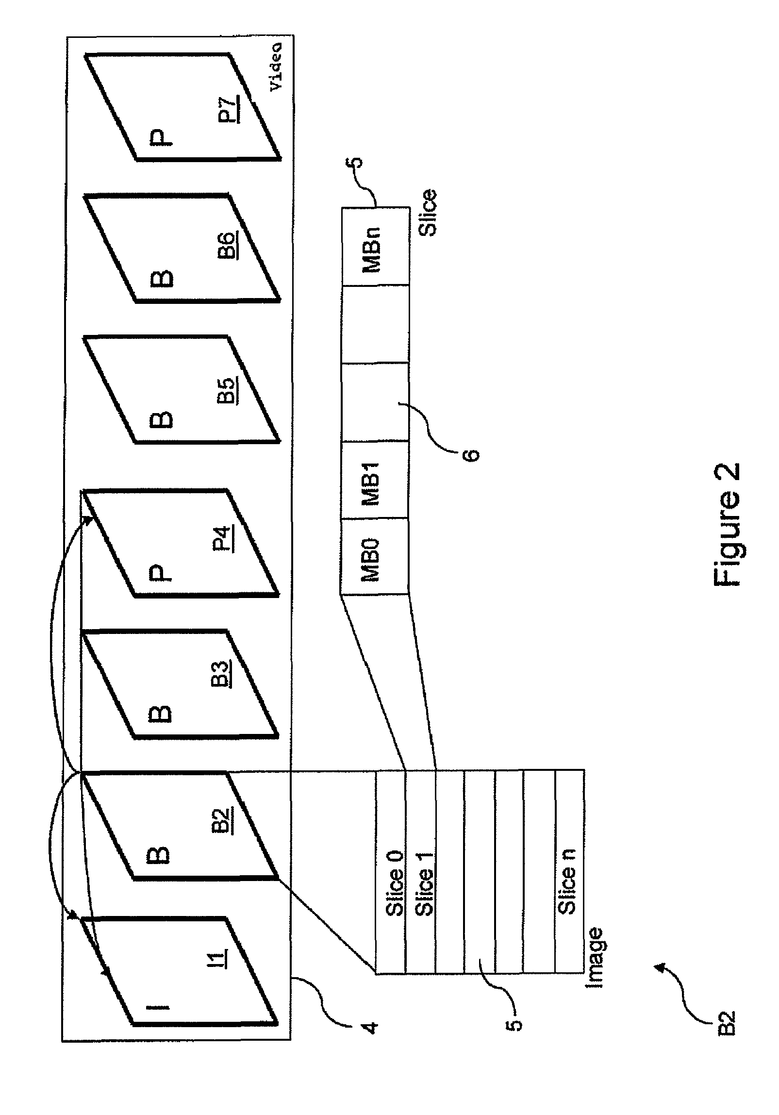
[0133]In a first embodiment, the previous image corresponds to the image decoded before the current image.

[0134]If we return to FIG. 2, it can be seen that the order of decoding of the first four images in the sequence of images is as follows: I1, P4, B2 and B3. Nevertheless, the display order is I1, B2, B3 and P4.

[0135]Thus, in this embodiment, if, for example, the image B2 is the current image, the previous image corresponds to the image P4.

[0136]The advantage of this embodiment is the simplicity of implementation with regard to the storage of data, since only the last decoded image has to be stored.

second embodiment

[0137]In a second embodiment, the previous image corresponds to the image preceding the current image in the order of display of the images in the sequence of images.

[0138]Thus, in the example in FIG. 2, the image preceding the current image B2 corresponds to the image I1.

[0139]The advantage of this embodiment is the use of a previous image that has high probabilities of resembling the current image.

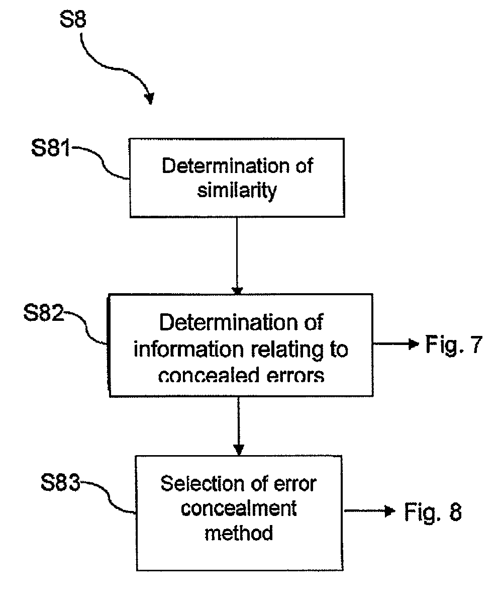
[0140]Once the degree / level of resemblance between the two images is determined, a step S82 of determining information relating to the errors concealed in the previous image is implemented.

[0141]In this determination step S82, the concealment of errors carried out at the previous image is taken into account. This step will be described in detail with the help of FIG. 7.

[0142]Results obtained during the comparison S81 and determination S82 steps are used during a selection step S83 in order to select the type of error concealment to be applied to the current image. The selection is made a...

third embodiment

[0197] the threshold Ti is determined using the following formula:

[0198]Ti=Ti-1+a⁡(mconc)×R1-b⁡(mintra)×R2withR1=number_concealed⁢_macroblocks⁢(i-1)total_number⁢_macroblocks⁢(i-1)⁢⁢R2=number_intra⁢_macroblocks⁢(i)total_number⁢_macroblocks⁢(i)mconc=concealment⁢⁢methodmintra=nature⁢⁢of⁢⁢INTRA⁢⁢coding

and in which:[0199]Ti is bounded by a predefined maximum value (Tmax) and minimum value (for example Ts),[0200]the parameters a and b have different values according respectively to the concealment method applied to the previous image i−1 and the nature of the INTRA coding in the current image i.

[0201]Thus a(mconc) has a predetermined value that depends on the result of the concealment method employed.

[0202]For example, when the error introduced by the concealment method is high, the value taken by the parameter a(mconc) is high.

[0203]On the contrary, when the error introduced by the concealment method is small, the value taken by the parameter a(mconc) is low.

[0204]By way of in no way lim...


PUM


Abstract

The invention concerns a method of concealing errors in at least one part of a current image (i) a sequence of images (4), characterized in that it comprises the following steps:comparing (S81) said at least one part of the current image (i) with at least one corresponding part of a previous image (i−1), andselecting (S83) a temporal error concealment method or a spatial error concealment method to be applied in said at least one part of the current image, according to the result of said comparison step and at least one item of information relating to the errors concealed in said at least one corresponding part of the previous image.

Description

FIELD OF THE INVENTION[0001]The present invention concerns an error concealment method.[0002]More particularly, it concerns a method of concealing errors in an image in a sequence of images.[0003]Correspondingly it concerns a device adapted to implement the method according to the invention.BACKGROUND OF THE INVENTION[0004]When a data stream, for example a sequence of images or video, is transmitted over a communication network, some data in the data stream are liable to be lost or corrupted.[0005]The consequence of the data loss or corruption that occurs during the transmission of a video sequence is the appearance of artifacts (or artificial interference) in some images in the video sequence. These artifacts reduce the quality of the video sequence.[0006]In order to improve the image quality, error concealment methods are applied to the images in the image sequence.[0007]The error concealment methods can be divided into temporal methods and spatial methods.[0008]Temporal methods c...

Claims


Application Information

Patent Timeline
Patent Type & Authority Patents(United States)
IPC IPC(8): G06K9/00H04N19/895
CPCH04N19/166H04N19/14H04N19/00157H04N19/00218H04N19/00242H04N19/00012H04N19/102H04N19/159H04N19/895H04N19/00939
Inventor OUEDRAOGO, NAELVANDAME, BENOIT
Owner CANON KK
Features
  • R&D
  • Intellectual Property
  • Life Sciences
  • Materials
  • Tech Scout
  • Unparalleled Data Quality
  • Higher Quality Content
  • 60% Fewer Hallucinations
Learn More