RF circuit system and method of increasing the isolation between two wireless communications standards within an RF circuit system
a technology of rf circuit system and rf circuit, which is applied in the field of wireless communication circuits, can solve the problems of insufficient isolation, interference amongst users, limited space available for internal circuitry, etc., and achieve the effect of eliminating unnecessary and interfering frequencies and improving isolation within wireless communication devices
- Summary
- Abstract
- Description
- Claims
- Application Information
AI Technical Summary
Benefits of technology
Problems solved by technology
Method used
Image


Examples
first embodiment
[0033]As shown in FIG. 2, according to this invention, an RF circuit system includes a first antenna 10, a first RF processing unit 11, a first transmitting suppressor 12 electrically coupled between the first antenna 10 and the first RF processing unit 11, a second antenna 20, a first isolation detector 21 electrically coupled to the second antenna 20, and a control unit 30 electrically coupled between the first transmitting suppressor 12 and the first isolation detector 21. The first RF processing unit 11 generates a first RF signal, which may be amplified by a power amplifier (PA) placed between the first RF processing unit 11 and the first transmitting suppressor 12. It is noted that “the first RF signal” referred to in the description hereinbelow has already undergone power amplification by the power amplifier (PA). The first transmitting suppressor 12 is able to transmit the first RF signal to the first antenna 10, which radiates that the first RF signal. The second antenna 20...
third embodiment
[0051]FIG. 7 shows the RF circuit system according to this invention, including, in addition to all of the elements shown in FIG. 5, a second isolation detector 16 electrically coupled between the first antenna 10 and the diplexer 14, a transmit-receive switch 23 coupled to the first isolation detector 21, a second RF processing unit 22, a second transmitting suppressor 24 electrically coupled between the second RF processing unit 22 and the transmit-receive switch 23, and a second receiving suppressor 25 electrically coupled between the second RF processing unit 22 and the transmit-receive switch 23. The second transmitting suppressor 24 and the second receiving suppressor 25 are the same or substantially similar in structure to that used in the first transmitting suppressor 12 as shown in FIG. 3, and each has a plurality of serially-connected filters (F1˜Fn) for filtering a third / fourth RF signal so as to generate a plurality of third / fourth suppressed RF signals respectively at o...
fourth embodiment
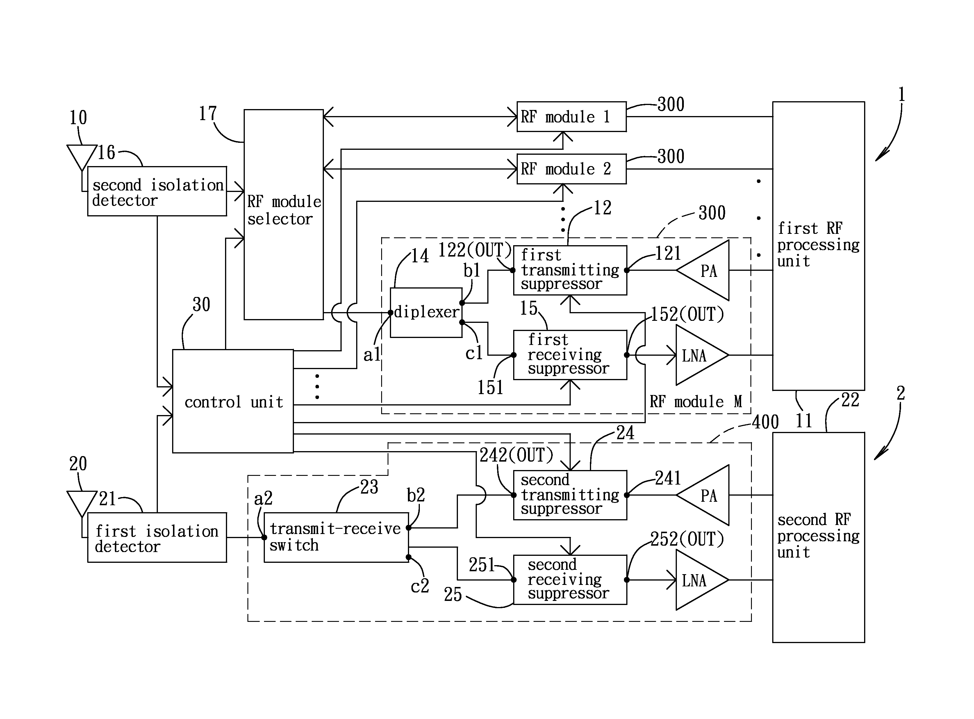
[0066]FIG. 10 depicts the RF circuit system according to this invention. The RF circuit system includes a first communications system 1, a second communications system 2, and a control unit 30 electrically coupled between the first communications system 1 and the second communications system 2. As an example, the first communications system 1 uses the LTE (Long Term Evolution) standard and includes a first antenna 10, a second isolation detector 16, a first RF processing unit 11, M number of RF modules 300, each working in a different frequency band, and an RF module selector 17 electrically coupled between the M number of RF modules 300 and the second isolation detector 16. Each of the RF modules 300 is the same as those depicted in FIGS. 5 and 7.
[0067]The second communications system 2 uses WiFi as an example, and includes a second antenna 20, a first isolation detector 21, a second RF processing unit 22, and an RF module 400 electrically coupled between the second RF processing u...
PUM
 Abstract
Description
Claims
Application Information
 - R&D
- Intellectual Property
- Life Sciences
- Materials
- Tech Scout
- Unparalleled Data Quality
- Higher Quality Content
- 60% Fewer Hallucinations
Browse by: Latest US Patents, China's latest patents, Technical Efficacy Thesaurus, Application Domain, Technology Topic, Popular Technical Reports.
© 2025 PatSnap. All rights reserved.Legal|Privacy policy|Modern Slavery Act Transparency Statement|Sitemap|About US| Contact US: help@patsnap.com