Check patentability & draft patents in minutes with Patsnap Eureka AI!

Surgical drape and method providing a sterile surface therewith

a sterile surface and surgical technology, applied in the field of surgical drapes, can solve the problems of increased possibility, high cost, and known risk of infection, and achieve the effects of reducing the risk of infection, and reducing the possibility of infection

Active Publication Date: 2014-08-19
ECO CATH LAB SYST
View PDF10 Cites 7 Cited by
  • Summary
  • Abstract
  • Description
  • Claims
  • Application Information

AI Technical Summary

Benefits of technology

The drape effectively provides a quick, economical, and user-friendly means to maintain sterility around radiation shields, minimizing bacterial transfer and reducing the need for extensive sterilization processes, while allowing for easy disposal and rapid reassembly, thus enhancing surgical safety and efficiency.

Problems solved by technology

The need to provide a sterile environment in a surgical theatre is directly associated with the known risk of infection that can be caused by bacteria, such as from a person or surgical equipment, in the surgical theatre.
Without surgical drapes, it becomes necessary to sterilize the surgical equipment thoroughly before and after each surgical procedure, which is labor intensive consuming a great deal of time, and thus, costly.
This requires having sterilization equipment available; is labor intensive, and thus, costly.
In addition, having to re-sterilize the drapes introduces an increased possibility that the reusable drape either not becoming completely re-sterilized, or that the re-sterilized drape becomes contaminated prior to future use, such as via improper repackaging.
In addition, the known disposable surgical drapes are challenging to deploy, both generally speaking and in proper fashion to maintain sterility, and non-conforming to the underlying surgical equipment upon being deployed.
As such, portions of the drapes are commonly baggy, thus, can get in the way of the transfer of surgical instruments between the anterior and posterior sides of the radiological shield during surgery.

Method used


Image

  • Surgical drape and method providing a sterile surface therewith
  • Surgical drape and method providing a sterile surface therewith
  • Surgical drape and method providing a sterile surface therewith

Examples


Embodiment Construction

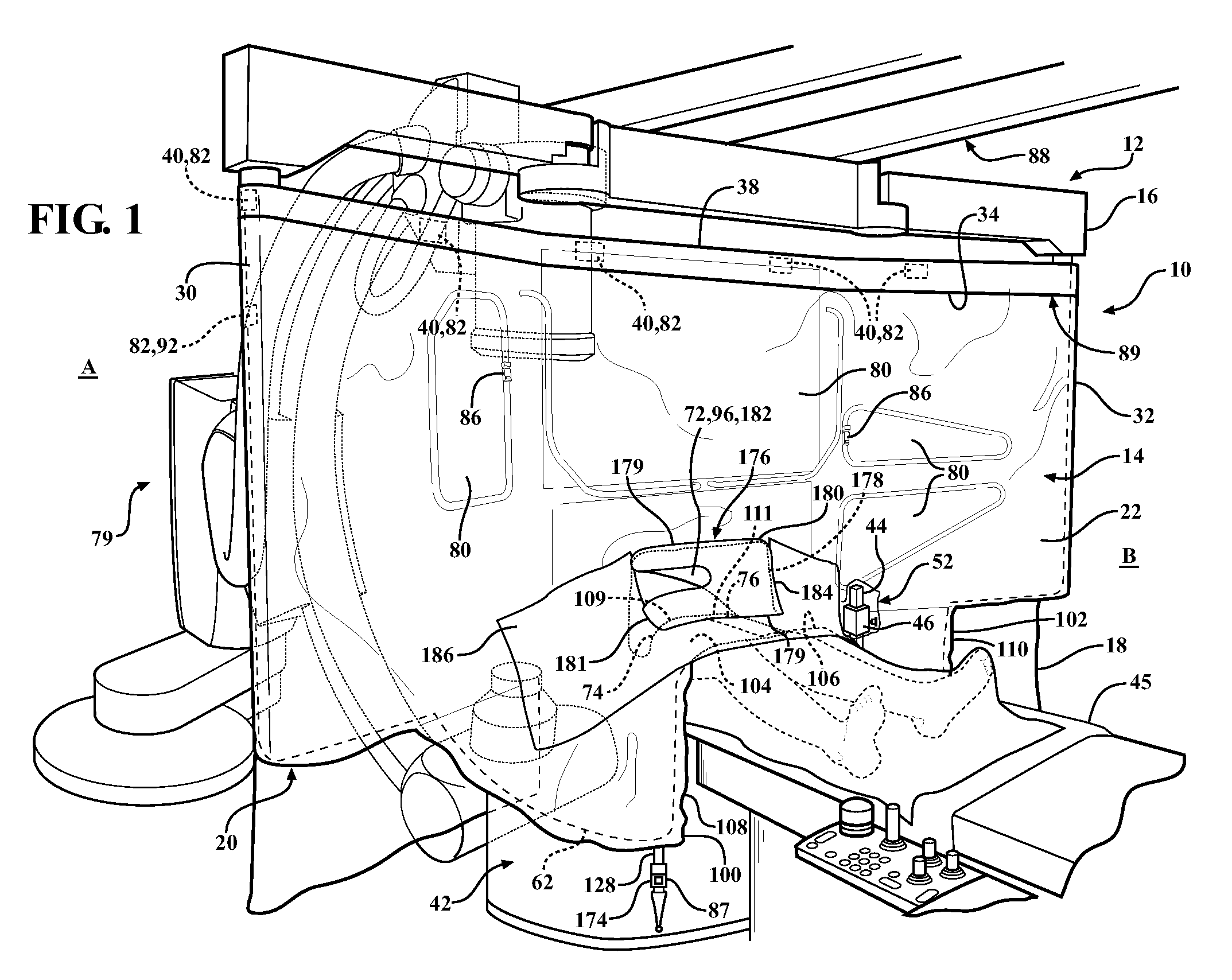
[0030]Referring in more detail to the drawings, FIG. 1 illustrates a disposable sterile surgical drape, referred to hereafter as drape 10, constructed in accordance with one aspect of the invention, with the drape 10 shown disposed about and enclosing a radiation shield assembly, referred to hereafter as radiation shield 12, such as a lead drape, to provide an outer sterile surface 14 about an upper portion 16 of the radiation shield 12. The drape 10 has a flexible, tear and puncture-resistant wall 18 substantially bounding an inner tubular cavity 20, wherein the cavity 20 is sized to receive the upper portion 16 of the radiation shield 12 therein. The flexible wall 18 has a front wall portion 22 configured to cover a front portion 24 of the radiation shield upper portion 16 and a rear wall portion 26 configured to cover a rear portion 28 of the radiation shield upper portion 16. The front and rear wall portions 22, 26 are joined to one another along opposite side edges 30, 32, such...


PUM


Abstract

A surgical drape and method of providing a sterile surface therewith is provided. The drape is configured to cover an upper portion of a radiation shield and includes a flexible wall providing a cavity sized to receive the upper portion of the radiation shield. The flexible wall has a rear wall portion configured to cover at least in part a rear portion of the radiation shield and a front wall portion configured to cover a front portion of the radiation shield. The front wall portion extends to an upper front free edge and the rear wall portion extends to an upper rear free edge. At least one fastener is attached to at least one of the front and rear wall portions adjacent respective ones of the upper front free edge and rear free edge. The fastener is configured to releasably fix the front and rear walls to the radiation shield.

Description

CROSS-REFERENCE TO RELATED APPLICATIONS[0001]This application claims the benefit of U.S. Provisional Application Ser. No. 61 / 269,235, filed Jun. 22, 2009, which is incorporated herein by reference in its entirety.BACKGROUND OF THE INVENTION[0002]1. Technical Field[0003]This invention relates generally to surgical drapes, and more particularly to disposable surgical drapes used to cover surgical equipment to maintain sterility in a surgical theatre.[0004]2. Related Art[0005]The need to provide a sterile environment in a surgical theatre is directly associated with the known risk of infection that can be caused by bacteria, such as from a person or surgical equipment, in the surgical theatre. As such, it is known that in order to minimize the risk of infection during a surgical procedure, it is necessary to prevent the transfer of bacteria, such as via airborne lint or dust particles, fluids, or otherwise, within the surgical theatre.[0006]Surgical drapes are commonly used during surg...

Claims


Application Information

Patent Timeline
Patent Type & Authority Patents(United States)
IPC IPC(8): A61B19/08A61B19/12A61B46/27
CPCA61N2005/1094A61B2019/0219A61B19/026A61N2005/1089A61N5/1077A61B2019/0267A61B19/10G21F3/00A61B19/081A61B2050/0065A61B2050/314A61B46/23A61B50/30A61B46/10
Inventor BYERS, TERRY M.TOURE, SAMBACZOP, MICHAEL W.WEAVER, RICHARD A.
Owner ECO CATH LAB SYST
Features
  • R&D
  • Intellectual Property
  • Life Sciences
  • Materials
  • Tech Scout
  • Unparalleled Data Quality
  • Higher Quality Content
  • 60% Fewer Hallucinations
Learn More